Pioneer qm 800 a owners manual

This is the 12 pages manual for pioneer qm 800 a owners manual.
Read or download the pdf for free. If you want to contribute, please upload pdfs to audioservicemanuals.wetransfer.com.

Page: 1 / 12
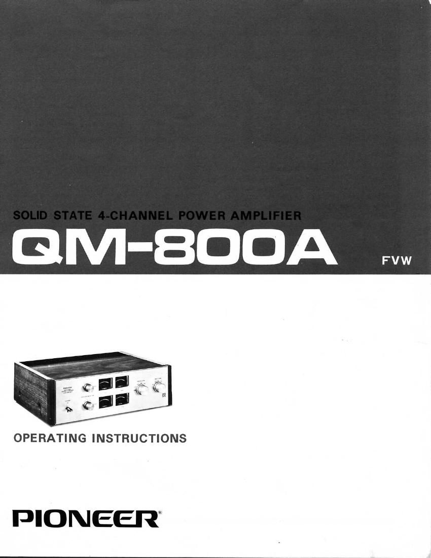
pioneer qm 800 a owners manual

Extracted text from pioneer qm 800 a owners manual (Ocr-read)


Page 1

GM-BDDA

OPERATING INSTRUCTIONS

PIONEER

Page 2

-

First, let us thank you for the confidence you have shown
us in purchasing the Pioneer 4-channel power amplifier,
model QM<800A. This amplifier is designed to serve in a 4-
channel stereo installation, together with a 4-channel pre-
amplifier, four speaker systems and one or several program
sources. Engineered for highest sound fidelity, it will open
up a whole new world of environmental sound." Please
read the following instructions carefully to assure that all
connections are made correctly and that the OM-800A
will reveal its true performance quality.

FEATURES

PURE COMPLIMENTARY OCL DESIGN

Matched pairs of specially selected, high power PNP and
NPN transistors are used. These top'grade audio
transistors possess unexcelled characteristics such as phase
accuracy, frequency response, linearity and minimum dis-
tortion.

DIRECT COUPLING OF ALL STAGES

Direct coupling of all amplifier stages greatly improves
phase characteristics and permits an extremely wide fre<
quencv response down to near-DC. A load-regulated power
supply unit is employed, and output power is higher than
will ever be required.

LEVEL METERS FOR ALL FOUR CHANNELS
To obtain optimum sound balance in a 4-channel system,
four separate level meters are provided. Moreover, the
meters sensitivity can be adjusted in three stages (0, -10,

-20 and -30 dB) to permit accurate readings at all volume
levels.

LINE VOLTAGE AND FUSE

CHANGING LINE VOLTAGE AND FUSE

TWO SPEAKER SYSTEMS CAN BE CON-
NECTED

The amplifier is equipped with two sets of speaker sockets,
providing for 4-channel reproduction in separate rooms.

ADJUSTABL E INPUT SENSITIVITY

As the power amplifier's input sensitivity can be adjusted
in 6:13 steps (at 0.5, 1, 2 and 5 volts), it is easy to match
with any preamplifier.

PERFECT PROTECTION OF OUTPUT STAGE
TRANSISTORS AND SPEAKERS

The output transistors are protected from damage (in the
case of overload or short-circuits in the speaker leads) by a
dual system of relay and DC driftvoltage detector circuits,
The latter also guard against possible speaker damage by
DC current.

UNIQUE PIONEER EXTERIOR DESIGN

The front panel is attractive as well as logically laid out.
With its natural wooden cabinet, the QM-BOOA matches
other Pioneer hi-fi components perfectly.

To remove the fuse, turn the fuse cap located on the line
voltage selector in the direction of the arrow. Then remove
the fuse plug from the unit.

Put the fuse plug back'so that the proper line voltage marking
can be seen through the cut in the edge of the plug, When-
ever the position of the selector is changed, check the rating
of the fuse. A 2-ampere is to be used for either 220V or
240V operation and a 4-ampere fuse for 110V, 120V, 130V
operation.

If the rating of the fuse is correct, replace cap.

FUSE REPLACEMENT
If the fuse blows, remove the fuse cap and replace the fuse
with a new one.

FUSE FUSE PLUG SOCKET

Take 01! the fuse can by turning ll With a coin, etc
in [Ill direction indicated by the anew mark.

COIN FUSE CAP