Pioneer pu 41 b owners manual

This is the 12 pages manual for pioneer pu 41 b owners manual.
Read or download the pdf for free. If you want to contribute, please upload pdfs to audioservicemanuals.wetransfer.com.

Page: 1 / 12
pioneer pu 41 b owners manual

Extracted text from pioneer pu 41 b owners manual (Ocr-read)


Page 1

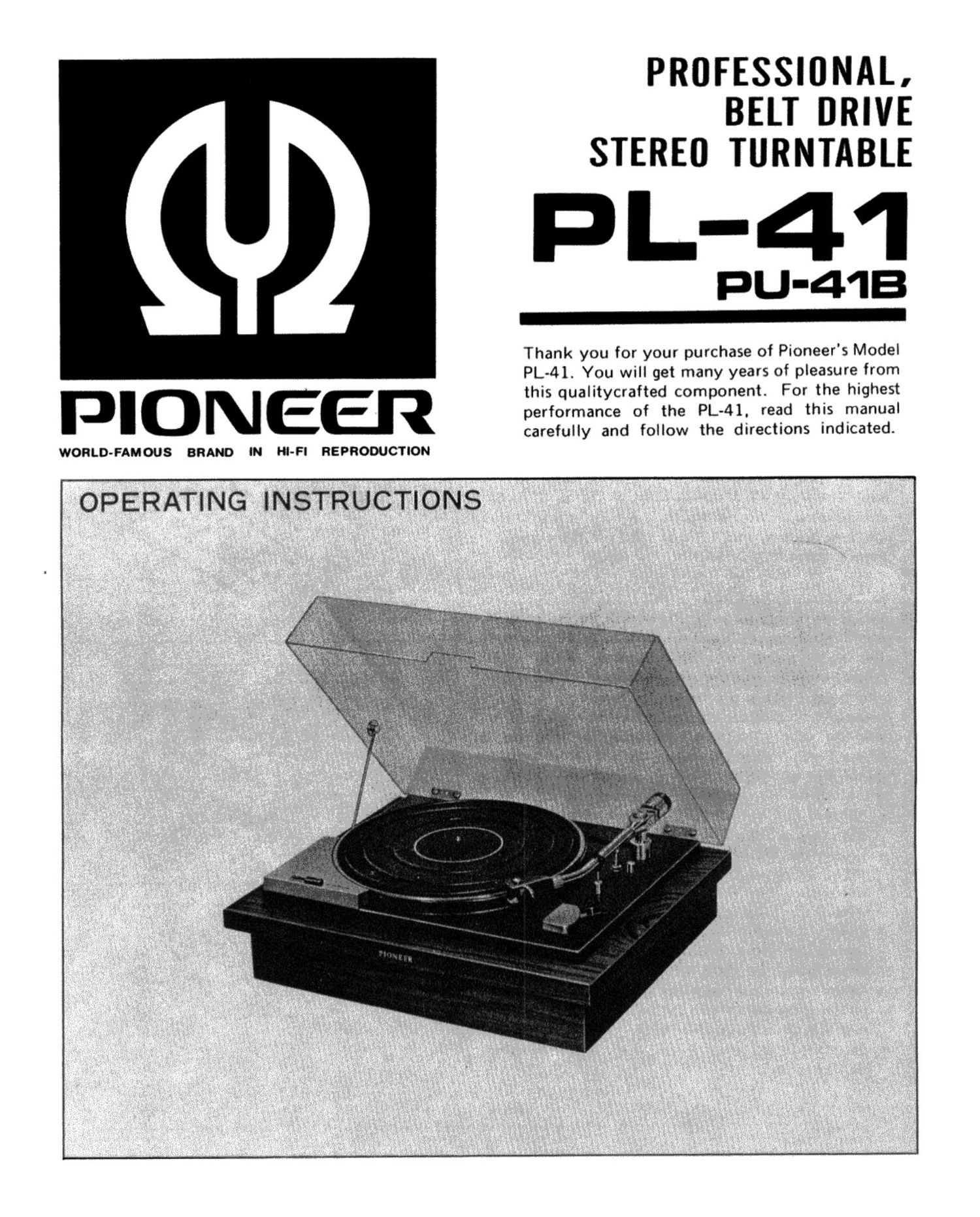
PIONEER

WORLD-FAMOUS BRAND IN Hl-Fl REPRODUCTION

PROFESSIONAL.
BELT DRIVE
STEREO TURNTABLE

PL-41

PU-41B

Thank you for your purchase of Pioneer's Model
PL-41. You will get many years of pleasure from
this qualitycrafted component. For the highest
performance of the PL-4l, read this manual
carefully and follow the directions indicated.

OPERATING INSTRUCTIONS

Page 2

ASSEMBLY

NOTE: The turntable platter will be found under a card-
board sheet in the lower portion of the packing case.

1.REMOVE THREE BASE PLATE CLAMPING
SCREWS.

The clamping screws are tipped with red paint. When they
are removed. the base plate is freed from the base plate
and supported by three suspension springs with plastic
cushions. (Fig. 1)

2. LINE VOLTAGE AND LINE FREQUENCY

A. LINE VOLTAGE SELECTOR SWITCH

Check the line voltage in your area before mounting the
turntable pletter on the unit.

Note. That Model PL-41 has been set to 220 to 240V line
voltage operation when delivered. If the line voltage in your
area is somewhere from 110V to 130V, set the line voltage
selector switch to 110 to 130V. (Fig. 2)

B. CAPSTAN EXCHANGE
Two kinds of capstans are furnished with the Model PL-41,
one for 50 Hz operation and the other for 60Hz operation.
The 50H: capstan has a larger diameter, and the 60H:
capstan, a smaller diameter with a weave in the lower part.
The Model PL-41 is usually set for operation of the line
frequency in the area to which it is shipped; however, if you
move to some other area m the line frequency is
different, you must change the capstan for proper tumteble
speeds. Find out the line frequency in your area and set the
proper capstan in your turntable as follows:

a You will find a capstan set up on the motor shaft and a
spare capstan laid on the base plate.

a Loosen two setscrews on the side of the capstan using
the smell screwdriver furnished in the accesory group,
endremove them. Then. pull out the capstan from the
motor shaft. (Fig. 3)

e Loosen the clamp that is holding the spare capstan,
remove the capstan from the resting place. and install it
on the motor shaft. (Fig. 3)

a Before tightening the setscrews. set the capstan in position
on the motor shaft so that the center of the belt is aligned
with that of the belt wideJFlQ- 4)

0 Set the line frequency switch to the proper frequency
position. (Fig. 3)

Fig. 1

220.240 VOLTS

Fig. 2

CAPSTAN
Lilli FREMNCY

CAPSTAN FOR use /
m 11-: 60H: an: 5mm"
ash
A seoove IS I- (-9
Q Q

CAPSTAN FOR USE
lN TlE 50 Hz AREA


1

Fig. 3

sum SELECT WW
('33'l8 IN n: mace POSITIM)

.__s
Threat-vanadium new.»
«firewalls Muesfiaalrated
nasal.

Fig. 4