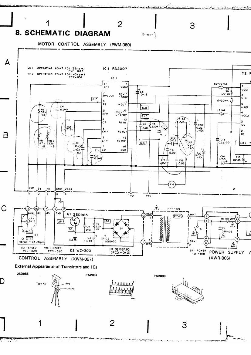
Pioneer pl 4 schematic
This is the 2 pages manual for pioneer pl 4 schematic.
Read or download the pdf for free. If you want to contribute, please upload pdfs to audioservicemanuals.wetransfer.com.
Extracted text from pioneer pl 4 schematic (Ocr-read)
Page 2
ICZ
can at A
I5-20mA
5
V REF
[Swan 4
: VCCZ
3
CC LA!
2 l3
RF L52
l 14
LEI YAB LAZ
CIS
10/35
NEUN
EL '046
Ac vows)? CORD
FOG-023
NER SUPPLY ASSEMBLY
IROOS)
5 , 6 pL-4
1. RESISTORS:
Indicated in n, %W. 25% tolerance unless otherwise noted k : kn,
M : Mn, (F) : 21%) (G) : $296. (K) 10% (M) :zzamoIar-m
2, CAPACITORS: A
Indicated in caoacitv (Fl/voltage (V) unles otherwise noted p : pF
Indication without voltage is 50V except electrolytic capacitor. 3
3. VOLTAGE, CURRENT:
E : DC voltage (V) at no input signal
(2:: mA : DC current at no input signal
4 OTHE RS:
@ :Adiusting point. _
The A\ mark found on some component parts indicates the im- f V
portance of the safety factor of the part. Therefore, when replacing,
be sure to use parts of identical designation)
This is the basic schematic diagram, but the actual circuit may vary
due to improvements in design.
SWITCHES:
s1: POWER 0N - OFF
52: SPEED 33l/3 rpm -45rpm
The underlined indicates the switch position)
6 1s