Pioneer pdf 1007 service manual

This is the 56 pages manual for pioneer pdf 1007 service manual.
Read or download the pdf for free. If you want to contribute, please upload pdfs to audioservicemanuals.wetransfer.com.

Page: 1 / 56
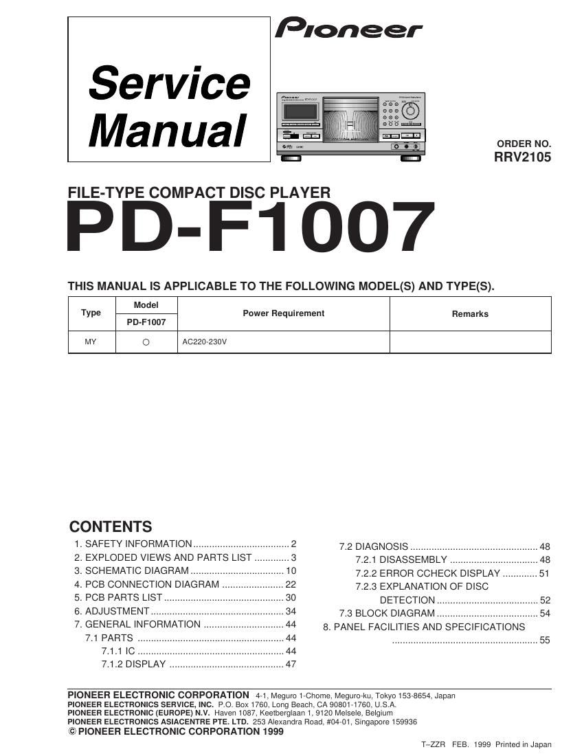
pioneer pdf 1007 service manual

Extracted text from pioneer pdf 1007 service manual (Ocr-read)


Page 1

PD-F1007 2Additional Laser Caution 1. Laser Interlock Mechanism The position of the switch (VSK1011) for detecting loading state is detected by the system microprocessor, and the design prevents laser diode oscillation when the switch (VSK1011) is not on CLMP terminal side (CLMP signal is OFF or high level). Thus, the interlock will no longer function if the switch (VSK1011) is deliberatery set to CLMP terminal side. (low level) The interlock also does not function in the test mode *. Laser diode oscillation will continue, if pin 33 of CXA1782CQ (IC151) on the MOTHER BOARD ASSY is connected to GND, or pin 89 of IC351 (LDON) is connected to low level (ON), or else the terminals of Q151 are shorted to each other (fault condition). 2. When the cover is opened, close viewing of the objective lens with the naked eye will cause exposure to a Class 1 laser beam. This service manual is intended for qualified service technicians; it is not meant for the casual do-it-yourselfer. Qualified technicians have the necessary test equipment and tools, and have been trained to properly and safely repair complex products such as those covered by this manual. Improperly performed repairs can adversely affect the safety and reliability of the product and may void the warranty. If you are not qualified to perform the repair of this product properly and safely, you should not risk trying to do so and refer the repair to a qualified service technician. 1. SAFETY INFORMATION IMPORTANT THIS PIONEER APPARATUS CONTAINS LASER OF CLASS 1. SERVICING OPERATION OF THE APPARATUS SHOULD BE DONE BY A SPECIALLY INSTRUCTED PERSON. REAR PD-F1007/MY LABEL CHECK * Refer to page 35 . LASER DIODE CHARACTERISTICS MAXIMUM OUTPUT POWER: 7 mw WAVELENGTH: 780 Ð 785 nm

Page 2

PD-F1007 3 1 6 8 910 11 12 1445 32 13 7 2. EXPLODED VIEWS AND PARTS LIST 2.1 PACKING PACKING PARTS LIST 1 Styrol Protector F PHA1325 2 Styrol Protector R PHA1326 3 Packing Case PHG2368 4 Packing Sheet RHC1023 5 Polyethylene Bag Z21Ð038 (0.03 ´ 230 ´ 340) 6 Operating Instructions PRD1052 (English/French/German/Italian) 7 Operating Instructions PRE1279 (Dutch/Swedish/Spanish/Portuguese) 8 Remote Control Unit PWW1139 (CD-PD094) 9 Battery Cover AZA7204 NSP 10 Dry Cell Batteries (R6P, AA) VEMÐ013 11 Control Cable (L=1 m) PDE1247 12 Audio Cable (L=1 m) PDE1248 NSP 13 Warranty Card ARY7022 14 KEY Board Label PRW1527 NOTES : Parts marked by Ò NSP Ó are generally unavailable because they are not in our Master Spare Parts List. The mark found on some component parts indicates the importance of the safety factor of the part. Therefore, when replacing, be sure to use parts of identical designation. Screw adjacent to mark on the product are used for disassembly. Mark No. Description Part No.