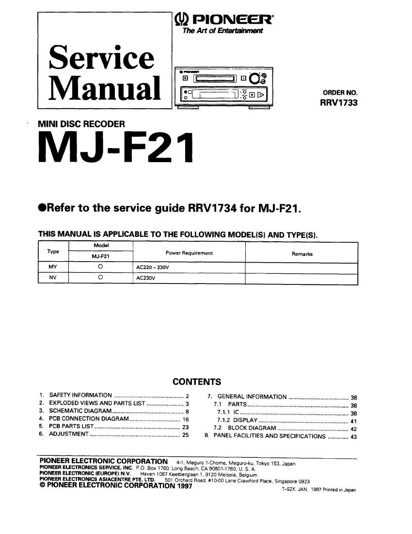
Pioneer mjf 21 service manual
This is the 44 pages manual for pioneer mjf 21 service manual.
Read or download the pdf for free. If you want to contribute, please upload pdfs to audioservicemanuals.wetransfer.com.
Extracted text from pioneer mjf 21 service manual (Ocr-read)
Page 1
(ID PIONEER
MeAnofEl-Itarfimm
Service ._..._ aw
M an a] gab-j 232'- a [> ORDER NO.
RRV1733
MINI DISC RECODER
MJ-F21
.Refer to the service guide RRV1734 for MJ-F21.
THIS MANUAL Is APPLICABLE TO THE FOLLOWING MODELISI AND TYPEISI.
Modal
TVPE MJ-F21 Power Requirement Remarks
MY 0 AC220 - 230v
NV 0 Aczaov
CONTENTS
I. SAFETY INFORMATION ........................ 7. GENERAL INFORMATION .
2. EXPLODED VIEWS AND PARTS LIST 7.1 PARTS...
3. SCHEMATIC DIAGRAM ......... 7.1.1 IC ........
4. PCB CONNECTION DIAGRAM.. 7.1.2 DISPLAY....
5. PCB PARTS LIST 7.2 BLOCK DIAGRAM
6. ADJUSTMENT
8. PANEL FACILITIES AND SPECIFICATIONS
PIONEER ELECTRONIC CORPORATION 4-1, Meguro 1-Chorne, Meguroku, Tokyo 1534 Japan
PIONEER ELECTRONICS SERVICE, INC. PO. Box 1760, Long Beach. CA 90801-1760, U. S. A,
PIONEER ELECTRONIC (EUROPE) N.V. Haven 1087 Keelberglaan 1, 9120 MelsaIe Belglum
PIONEER ELECTRONICS ASIACENTRE PTE. LTD. 501 Orchard Road, $10-00 Lane Crawford Place. Singapore 0923
© PIONEER ELECTRONIC CORPORATION 1997 TfigzK JAN 1997 primed in Japan
Page 2
MJ-F21
1. SAFETY INFORMATION
-VARO!---
AVATTAESSA JA SUOJALUKITUS
OHITETTAESSA OLET ALTTIINA
NAKYMATTOMALLE LASERSATEILYLLE.
ALA KATSO SATEESEEN.
LASEFI
Kuva 1
- ADVARSEL: Lasersaleilyn
USVNLIG LASERSTHALING VED ABNING varoitusmerkki
NAFI SIKKEFIHED SAFBHYDERE ER UDE
AF FUNKTION. UNDGA UDSEI'I'ELSE FOFt
STRALING.
- VAHNING ! -__-
OSYNLIG LASERSTHALNING NAR DENNA
DEL AFI OPPNAD OCH SPAFIHEN
3H URKOPPLAD. BETRAKTA EJ STRALEN.
- WARNING ! -
DEVICE INCLUDES LASER DIODE WHICH
EMITS INVISIBLE INFRARED RADIATION
WHICH IS DANGEROUS TO EYES. THERE Is
A WARNING SIGN ACCORDING TO PICTURE
1 INSIDE THE DEVICE CLOSE ro THE LASER LASER
DIODE. Picture I
Warnlng sign lor
IMPORTANT
laser radiation
THIS PIONEER APPARATUS CONTAINS
LASER 0F CLBS I.
SERVICING OPERATION OF THE APPARATUS
SHOULD BE DONE BV A SPECIALLY
INSTRUCTED PERSON.
AXIMUM OUTPUT POWER: 5 mw
ELENGTH' 750 - 785 nm
- LASEFI DIODE CHARACTERISTICS -
M
LABEL CHECK
Additional Laser Caution
I. Laser Interlock Mechanism
The position at the switch (SW1958) for detecting loading
state is detected by the MD mechanism microprocessor
001401). and the design prevents laser diode oscillation
when the switch (SW1956) is OFF (Pin 6 of IC1401 is high
level.) Thus. the interlock will no longer lunction it the
switch (SW1956) is deliberately set to ON. (Pin 6 ol
ICI4DI is low level.)
The interlock also does not lunctiDn in the test mode'.
Laser diode oscillation will continue, it pin 20 of IR3FI50
(lC1101) is connected to GND, or else the terminals
(between emitter and collector) ul 01101 are shorted to
each other.
2. When the cover is opened, and the shielding case at MD
mechanism unil (FlYM1257) is further opened. close
viewing of the objective lens with the naked eye will cause
exposure to a Class 1 laser beam.
* Refertopage 25.
MYINV types
VW!
halal-Ill )- Imjllulll Al-Ill-
.tuum nllyllllb-lll
nym. Au Inna nun"...
VWXMI
gum. up l-nnl an
A: man lfllrln l: manila.
mu: u- .
I if I In W