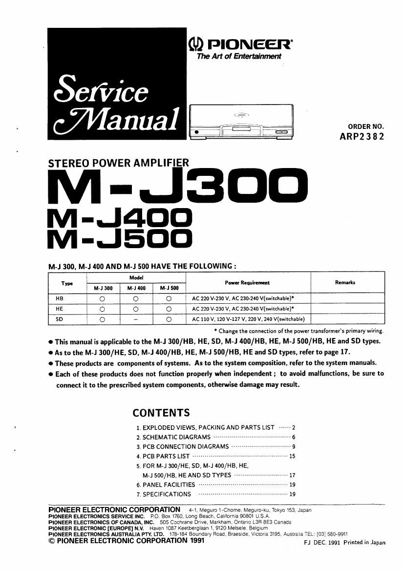
Pioneer mj 500 service manual
This is the 15 pages manual for pioneer mj 500 service manual.
Read or download the pdf for free. If you want to contribute, please upload pdfs to audioservicemanuals.wetransfer.com.
Extracted text from pioneer mj 500 service manual (Ocr-read)
Page 1
GD PIONEER
The Art of Entertainment
ORDER NO.
ARP2 3 8 2
STEREO POWER AMPLIFIER
M -J3DD
M-J4DD
M-JEDD
M-J 300, M-J 400 AND M-J 500 HAVE THE FOLLOWING :
Model
Type Power Requirement Remarks
M
HE C o 0 Ac 220 vvzso v. AC 230-240 V(switchable)*
SD 0 - O AC 110 V. 120 V-127 V. 220 V, 240 V(switchable)
Change the connection of the power transformers primary wiring.
O This manual is applicable to the M-J BOO/H3, HE. SD, M-J 400/HB, HE, M-J 500/HB, HE and SD types.
0 As to the M-J 300/HE, SD, M-J 400/HB. HE, M-J SOD/H3. HE and SD types. refer to page 17.
0 These products are components of systems. As to the system composition, refer to the system manuals.
0 Each of these products does not function properly when independent ; to avoid malfunctions. be sure to
connect it to the prescribed system components. otherwise damage may result.
CONTENTS
1. EXPLODED VIEWS, PACKING AND PARTS LIST ------ 2
2- SCHEMATIC DIAGRAMS ....................................... 6
3. PCB CONNECTION DIAGRAMS ----------------- 9
4. PCB PARTS LIST ------------------------------- ~~ 15
5. FOR M-J SOD/HE, so, M-J 4oo/HB, HE,
M-JSOO/HB, HEAND so TYPES ........................... 17
5. PANEL FACILITIES .. -19
7. SPECIFICATIONS .. 19
PIONEER ELECTRONIC CORPORATION 4-1. Megurc 1-Chome. MegurO-ku, Tokyo 153, Japan
PIONEER ELECTRONICS SERVICE INC. PO Box 1760, Long Beach, Calllorma 90801 US A
PIONEER ELECTRONICS OF CANADA, INC. 505 Cachrane Drive, Markham. Ontano L3H 8E3 Canada
PIONEER ELECTRONIC [EUROPE] N.V, Haven 1087 Keetberglaan I, 9120 Melsele. Belgium
PIONEER ELECTRONICS AUSTRALIA PTY. LTD. 178-184 Boundary Road. Braeside, VICIorIa 3195. Auslraha TEL: [03] 5803911
© PIONEER ELECTRONIC CORPORATION 1991 FJ DEC. 199, mm, in Japan
Page 2
M-JSDD
1. EXPLODED VIEWS, PACKING AND PARTS :LIST
NOTES:
0 The parts with an encircled number are generally unavailable because they are not in tam-Master Spare Parts List.
0 The A mark found an some component parts indicates the importance of the safety factor of the part. Therefore, when replacing,
be sure to use parts of identical designation.
0 Parts marked by O are not always kept in stock Their delivery time may be longer than usual or they may be unavailable.
1.1 PARTS LIST
Mail: No. Description Parts No. Mark No. Description Parts No.
1. POWER BUTTON AAD2109 A 31. CAPACITOR FOR POWER (Cl) ACG1003
2. INDICATOR LENS(PLS) AAK2224 A 32. FUSE (FU1,4A) AEK-511
3. BTYTE ABA1093 33. SCREW ABA1147
4. BIND B TYTE ABA-298 34. BIND B TYTE ABAIOOQ
5. B TY'IE ABA1011 35. CONNECTOR CABLE(.I) ADE1117
6. BIND 3 x 1813 TYTE ABAIOIS A 36. TRANSISTOR(03, Q4) 2SA1302
7. B TYTE 3 x 10 ABA-283 A 37. PUSE (PU. 4A)(SD only) ARK-511
8. B TYTE 3 X 14 ABA1082 A 33. TRANSISTOR(Q1, Q2) 2503281
9. P TYTE 2.6 x s ABA1095 39. REINFORCED PLATE ANG1635
10. POWER BUTTON SPRING ARI-11079 A 40. PUSH SWITCH(SI) Ascwss
A 11. POWER CORD ADCnoa A 41. POWERTRANSPORMER(T1) ATS1330
A 12. AC CORD STOPPER AEc-ssz O 42. POWER ASS'Y AW23783
13. PCB SUPPORT AEc1010 O 43. POWER SW ASSY AWZ3789
14. FOB SUPPORT AEc1216 ® 44. TRANS CONNECT ASSY AWZ3792
15. PCB SPACER AE01303 © 45. SP TERMINAL ASSY AW23793
1s. BINDER AEP-zls © 46. SP SW ASSY sza790
17. MIKA SHEET AEE1014 © 47. LED ASSY AW23813
18. FRONT PANEL ASSY AMBIsm © 48. HEAD PHONE ASSY AWZ4116
19. PCB MOLD AMR1525 49. FOOT ASS'Y AMR1937
20. CHASSIS ANA1161
A 50. VOLTAGE SELECTOR AKXASO7
21. REAR PANEL ANC1795 51. SPEAKER KNOB AAD21o7
22. BONNET(MTL) ANE1320 52. SPEAKER KNOB AADz14s
23. P c B HOLDER ANG1609
24' .. ..
25. CHASSIS COVER ANG1627
26. HEAT SINK ANH1266
27. SCREW BBZZGPOBOFMC
28. SCREW BCZSOPIODFZK
29. FOOT ASSY(ABS) RXA1448
so. BINDER ABC-826