Pioneer kexm 9176 zt service manual

This is the 84 pages manual for pioneer kexm 9176 zt service manual.
Read or download the pdf for free. If you want to contribute, please upload pdfs to audioservicemanuals.wetransfer.com.

Page: 1 / 84
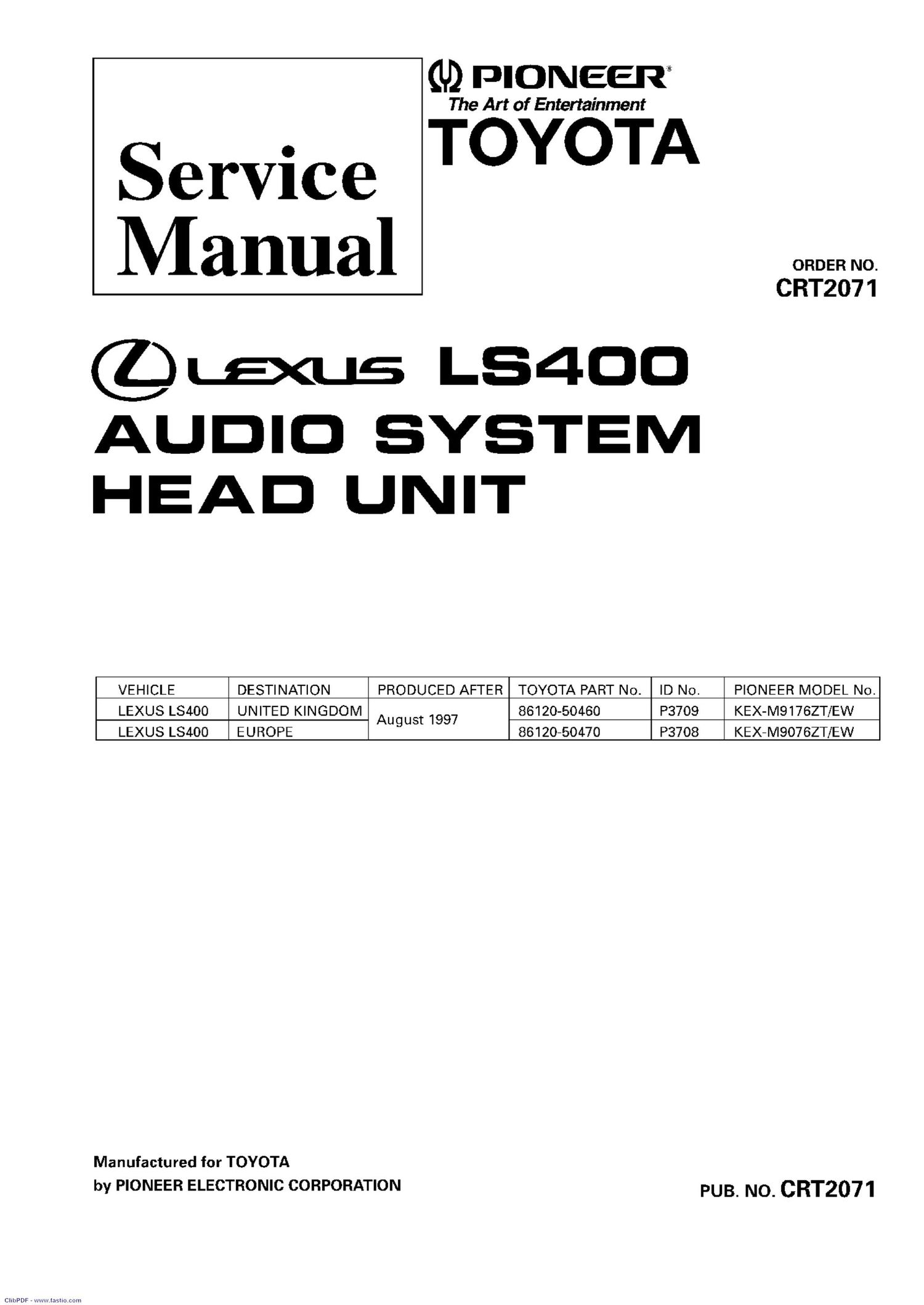
pioneer kexm 9176 zt service manual

Extracted text from pioneer kexm 9176 zt service manual (Ocr-read)


Page 2

KEX-MQI7BZT, MQI7EZT-9'I, MQO7BZT, M907BZT-9'I

KEX-M9176ZT/EW

WEWWGL

r
ASH.
\

WU __ f

TUNE

SEEK
DRAW

ID NO. P3709

KEX-M9076ZT/EW

[POWER-MOI].

ID NO. P3708

. Dolby noise reduction manufactured under license from Dolby Laboratories Licensing Corporation.

"Dolby" and the double-D symbol are trademarks of Dolby Laboratories Licensing Corporation.

0 See the separate manual CX-529 (CRT1507) for the cassette mechanism description.

0 The cassette mechanism employed in this model is one of 2L mechanism description.

0 This service manual does not describe the CD test mode.

For the operations in the CD test mode, refer to the CD player's Service Manual.

. Supplementaly model is identical to the original except for the addition of following items.

Description

Part No.

KEX-M9176ZT-91/EW
KEX-M9076ZT-91/EW

Polyethylene Bag ' CEG1026

Carton CHA2025

Contain Box CHD2025

Protector CHP1678

Protector CHP1678

CONTENTS

1. SAFETY INFORMATION ............................................ 3
2. EXPLODED VIEWS AND PARTS LIST ....................... 4
3. SCHEMATIC DIAGRAM ........................................... 10
4. PCB CONNEC ION DIAGRAM ................................ 24
5. ELECTRICAL PARTS LIST ........................................ 41
6. ADJUSTMENT .......................................................... 49

CIibPDF - www.fasl ooooooo

7. GENERAL INFORMATION ....................................... 59
7.1 PARTS ................................................................ 59
7.1.1 IC .............................................................. 59

7.1.2 DISPLAY ................................................... 64

7.2 DIAGNOSIS ....................................................... 68
7.2.1 DIAGNOSIS MODE ................................. 68

7.2.2 ANTI-THEFT SECURITY SYSTEM .......... 72

7.2.3 DISASSEMBLY ........................................ 76

7.2.4 CONNECTOR FUNCTION DESCRIPTION ..77

7.3 EXPLANATION .................................................. 78
7.3.1 BLOCK DIAGRAM ................................... 78

7.3.2 SYSTEM BLOCK DIAGRAM ................... 80

8. OPERATIONS AND SPECIFICATIONS ..................... 81