Pioneer jar 106 owners manual

This is the 4 pages manual for pioneer jar 106 owners manual.
Read or download the pdf for free. If you want to contribute, please upload pdfs to audioservicemanuals.wetransfer.com.

Page: 1 / 4
pioneer jar 106 owners manual

Extracted text from pioneer jar 106 owners manual (Ocr-read)


Page 1

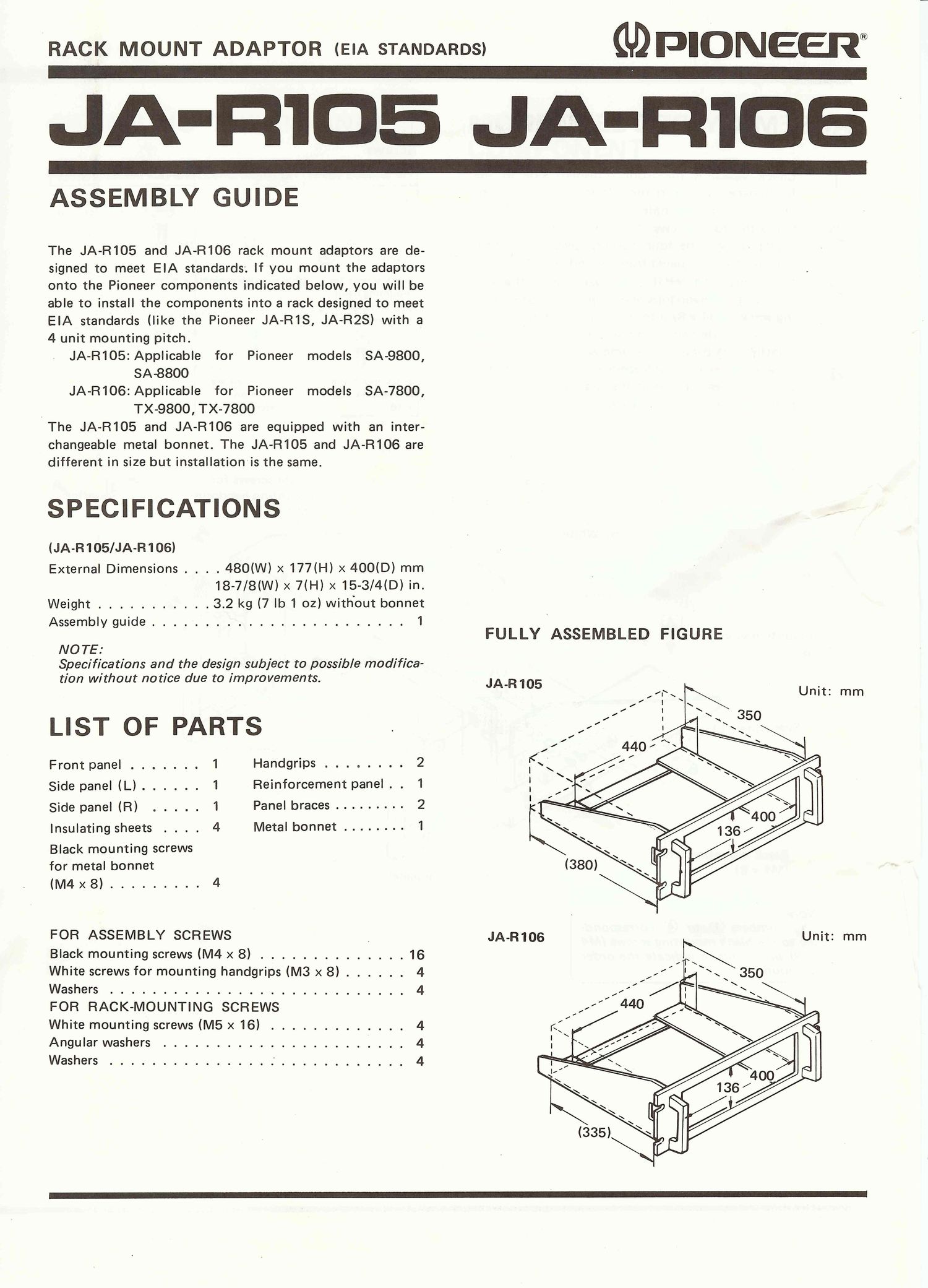
RACK MOUNT ADAPTOR (EIA STANDARDS) GDFICMVEEI?®

-105 LIA-ID

ASSEMBLY GUIDE

The JA-R105 and JA-R106 rack mount adaptors are de-
signed to meet EIA standards; If you mount the adaptors
onto the Pioneer components indicated below, you will be

able to install the components into a rack designed to meet
EIA standards (like the Pioneer JA-R1S, JA-RZS) with a
4 unit mounting pitch.

JA-R1052Applicable for Pioneer models SA-9800,

SA-88OO

JA-R106zApplicable for Pioneer models SA-7800,
1 TX-9800, TX-78OO
The JA-R105 and JA-R106 are equipped with an inter-
changeable metal bonnet. The JA-R105 and JA-R106 are
different in size but installation'is the same.

SPECIFICATIONS

(JA-R105/JA-R106)

External Dimensions . . . . 480(W) x 177(H) x 400(D) mm
18-7/8(W) x 7(H) x 15-3/4(D) in.
Weight ........... 3.2 kg (7 lb 1 oz) with'out bonnet
Assembly guide ........................ 1
FULLY ASSEMBLED FIGURE
NOTE:
Specifications and the design subject to possible modifica-
tion without notice due to improvements. JA-R105

«x Unit: mm

LIST OF PARTS

Front panel ....... 1 Handgrips ........ 2
Side panel (L) ...... 1 Reinforcement panel . . 1
Side panel (R) ..... 1 Panel braces ......... 2
Insulating sheets . . . . 4 Metal bonnet ........ 1

Black mounting screws
for metal bonnet

(M4 x 8) ......... 4

FOR ASSEMBLY SCREWS _ JA-R106 Unit: mm
Black mounting screws (M4 x 8) .............. 16 )\

White screws for mounting handgrips (M3 x 8) ...... 4 / \ \

Washers ............................ 4

FOR RACK-MOUNTING SCREWS

White mounting screws (M5 x 16) ............. 4

Angular washers ....................... 4

Washers ................ ............ 4

Page 2

ASSEMBLY PROCEDURE

Black mounting screws
(M4 x 8)

Check which is the front (finished) side of the
front panel and insert the left and right handgrips
into the front panel holes.

Using the four screws (M3 x 8) for mounting the
handgrips and the four washers, secure the hand-
grips to the front panel from behind (Fig. 1).

Next, align the left(L) side panel with the side
panels of the handgrips and, insert the four mount-
ing screws (M4 x 8) into the mounting holes on the
handgrips side panels and secure. Then secure the
righth) side panel in the same way.

Finally, align the reinforcement panel and fasten
securely from the top of the side panels using the
four mounting screws (M4 x 8).

White screws for

mounting handgrip
(M3 x 8)

Reinforcement
panel

In
2':

'J


Side panel (L)

Black mounting screws
(M4 x 8)

Note:
The numbers G) to @ correspond-

ing to the black mounting screws (M4
x 8) in the figure indicate the order
of mounting.

\ Front panel

\x

Q}

Screws

For assembly screws For bonnet screws For rack mounting screws

White screws White screws
for mounting Q
handgfip

(M5X16)X4
(M3x8)x4 i

Washer x 4
@ Angular washers
x 4

For metal bonnet

Black screws for
mounting hand-
grip and mounting
the component )

Black mounting
screws (M4 x 8)
x 16

|For wooden cabinet


@ Vinyl washers
x 4

These screws are
provided on
_ wooden cabinet

Table 1

White screws for
mounting handgrip
(M3 x 8)

Side panel (R) Black mounting

screws (M4 x 8)

Handgrips

Mounting holes for side panel

Fig. 1