Pioneer jar 102 owners manual
This is the 1 pages manual for pioneer jar 102 owners manual.
Read or download the pdf for free. If you want to contribute, please upload pdfs to audioservicemanuals.wetransfer.com.
Extracted text from pioneer jar 102 owners manual (Ocr-read)
Page 1
RACK MOUNT ADAPTOR (EIA STANDARDS)
ASSEMBLY GUIDE
A-RIIDE GDPIONEER
The )A-R102 rack mount adaptor is designed to meet EIA
standards. If you mount the adaptor onto the Pioneer
stereo cassette tape deck with dimensions like those indi-
cated in the Fig. 2 below, you will be able to install the
deck into a rack designed to meet EIA standards (like the
Pioneer JA~R25) with a 4 unit mounting pitch.
Provide yourself with a mediumrsizcd Phillips screwdriver,
MOUNTING P ROCEDURE
The JA-R102 adaptors are mounted on the left-
hand and right-hand sides of the cassette tape
decks front panel. The parts can be used for either
side but the side panels have a front and a reverse
side. Make sure that you mount the side panels so
that the side with the same finish as the front panel
faces you.
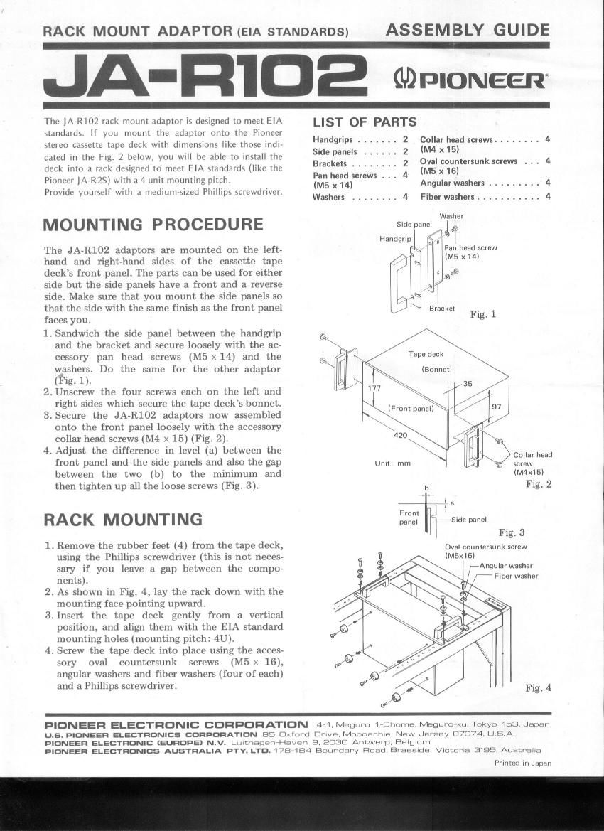
1. Sandwich the side panel between the handgrip
and the bracket and secure loosely with the ac-
cessory pan head screws (ME x 14) and the
washers. Do the same for the other adaptor
(Fig. 1).
2. Unscrew the four screws each on the left and
right sides which secure the tape decks bonnet.
3. Secure the JA~R102 adaptors now assembled
onto the front panel loosely with the accessory
collar head screws (M4 x 15) (Fig. 2).
4. Adjust the difference in level (a) between the
front panel and the side panels and also the gap
between the two (b) to the minimum and
then tighten up all the loose screws (Fig. 3).
RACK MOUNTING
1. Remove the rubber feet (4) from the tape deck,
using the Phillips screwdriver (this is not neces-
sary if you leave a gap between the compo-
nents).
2. As shown in Fig. 4, lay the rack down with the
mounting face pointing upward.
3. Insert the tape deck gently from a vertical
position, and align them with the EIA standard
mounting holes (mounting pitch: 4U).
4. Screw the tape deck into place using the acces-
sory oval countersunk screws (N15 x 16),
angular washers and fiber washers (four of each)
and a Phillips screwdriver.
LIST OF PARTS
Handgrips ....... 2 Collar head screws ........ 4
Side panels ...... 2 (M4 X15)
Brackets ________ 2 Oval countersunk screws . . . 4
Pan head screws . . . 4 (M5 X16)
(M5 x 14) Angular washers ......... 4
Washers ........ 4 Fiber washers ........... 4
Washer
Side panel if
4 a i
Handgrip 3"
i (Pan headscrew
(M5 x 14)
a
Bracket _
Fig. 1
Tape deck
(Bonnetl
:>
Collar head
screw
(M4X15l
b Fig. 2
a
Slde panel
Fig. 3
Oval countersunk screw
(M5x16l
i ,-Angular washer
i
r /7 Fiber washer
PIONEER ELECTRONIC CORPORATION 44,Megnr»o nanome. Mcgumekunokye i53. Japan
u.s. PIONEER ELECTRONICS coupon/anon 85 Oxmm Dr'lve. Mommasma, New Jersey 07074, [J 5 A
PIONEER ELECTRONIC (EUROPE) N.V. LutthagE-flet-(averi 9. 2030 Amtwerp. Belgiurh
PIONEER ELECTRONICS AUSTRALIA p'rv. LTD. 178-184 Boundary Fload, Braeslde. VichDrla 3195, Australia
Printed in Japan