Pioneer jar 101 owners manual

This is the 2 pages manual for pioneer jar 101 owners manual.
Read or download the pdf for free. If you want to contribute, please upload pdfs to audioservicemanuals.wetransfer.com.

Page: 1 / 2
pioneer jar 101 owners manual

Extracted text from pioneer jar 101 owners manual (Ocr-read)


Page 1

RACK MOUNT ADAPTOR (EIA STANDARDS)

ASSEMBLY GUIDE

A-Fncn men

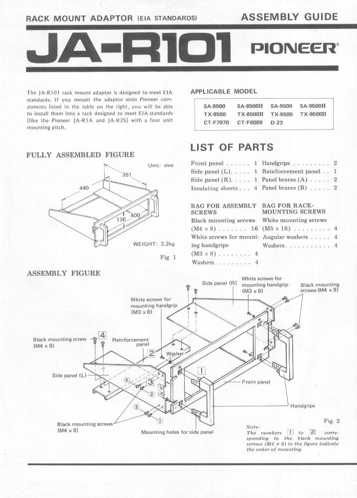
The JA-RlOi rack mount adaptor is designed to meet EIA
standards. If you mount the adaptor onto Pioneer com-
ponents listed in the table on the right, you will be able
to install them into a rack designed to meet EIA standards
(like the Pioneer lA-RIA and lAvR2S] with a four unit
mounting pitch.

FULLY ASSEMBLED FIGURE

WEIGHT: 32kg

Fig 1

ASSEMBLY FIGURE

White screws ior
mounting handgrip

Black mounting screw
1M4 x B)

Side panel (L)

Black mounting screws
(M4 x 8)

Mounting holes for side panel

APPLICABLE MODEL

SA-8500 SA-850011 SA-9500 SA-QSOOII
l
TX»8500 TX-8500" TX-9500 TX~9500H
1 CT-F7070 CT-FBOBO 0-23
l

LIST OF PARTS

Front panel ...... 1 Handgrips ......... 2
Side panel (L) ..... 1 Reinforcement panel l . 1
Side panel (R) ..... 1 Panel braces (A) ..... 2
Insulating sheets i . , 4 Panel braces (B) ..... 2

BAG FOR ASSEMBLY BAG FOR RACK-

SCREWS MOUNTING SCREWS
Black mounting screws White mounting screws
(M4 x8) ....... 16 (M5x16) ......... 4
White screws for mount- Angular washers ..... 4
ing handgrips Washers ........ 4
(M3 x 8) ........ 4

Washers ......... 4

White screws for
mounting handgrip
(M3 x 8)

Side panel (R) Black mountin

screws (M4 x B

l:

F ront panel

Handgrips

Fig, 2
Nate: , k

The numbers ,n to gl corre-
spandx'ng to the black mounting
screws (M4 X 8} in 12 figure indicate
the order of mounting.

Page 2

ASSEMBLY PROCEDURE

iIi Check which is the front (finished) side of
the front panel and slot in the handgrips
both left and right.

Using the four screws (M3 x 8) for mounting
the handgrips and the four washers. secure
the handgrips to the front panel from
behind (Fig. 2).

MOUNTING THE COMPONENT


Panel brace

/ /
Front panel Front panel of
component

Front panel of
component

- PIONEER

Next, align the left (L) side panel with the
side panels of the handgrips and, using the
four mounting screws (M4 x 8), insert into
the mounting holes on the handgrips' side
panels and secure. Then secure the right (R)
side panel in the same way.
Finally, align the reinforcement panel and
fasten securely from the top of the side
panels using the four mounting screws (M4 X
8).

Slide the component into the adaptor as
shown in Fig. 3,

E]

Make sure that the front panel of the
JA-RlOl adheres closely to the front panel
of the components.

Tighten the panel braces (both A and B)

n

Panel brace Front panel [3
A or B i . of JA-R101 with the four mounting screws (M4 X 8) and
6 w then secure the audio component from both
:7 sides.
Black mounting screws (M4x8l Fig. 3
PANEL BRACES Unit; mm
12 Jx «6 .
. / \ Use the brace marked A for the followmg com-

Fig. 4

F0 r CT-F8080

ponents available from Pioneer: CT-F7070.
SA-850011. SA-950011, TX-85OOII, TX-BSOOII,
D-23,etc.

Use the brace marked B for the Pioneer
CT'FSOBO only. You cannot use it for any other
Pioneer components.

Mou nting screw

(M5x16l T7

Angular

washer
Washerg

Front panel of \
component
Peel 0" the

reverse side
of the sheet


1] As shown in Fig. 5, lay the rack (must meet

EIA standards like the JA-RlA or the JA-

RZS) down with the mounting face pointing
upward.

Insert the components gently from a vertical
position, and align them with the EIA stand-
ard mounting holes (mounting pitch: 4U).

Screw the components into place using the
accessory screws (M5 x 16), angular washers
and washers (four of each) and a Phillips
screwdriver.

USING THE INSULATING SHEETS

These sheets are designed to insulate the set when it
is incorporated into a metal rack. If they are
adhered to the reverse side of the front panel, they
can help reduce noise.

As shown in the Fig. 5, attach these sheets to the
four mounting holes on the front panel.

PIONEER ELECTRONIC CORPORATION 4-1 MegurD loCthe, Meguloiku Tokyo 153, Japan
u.s. PIONEER ELECTRONICS GDRDDHATIDN 85 Oxford Dove. Moonoomo, New Jersey 07074, us A
DIONEEH ELECTRONIC [EUROPE] N.V. LumhagenoHaven 9. 2030 Aanerp. Eelglum

PIONEER ELECTRONICS AUSTRALIA ia'rv. LTD. 1787184 Boundary Road, BPEE-zside. Vicmria 315:5, Anon-ens

Printed in Japan (ARA-10343)