Pioneer gx 646 service manual

This is the 72 pages manual for pioneer gx 646 service manual.
Read or download the pdf for free. If you want to contribute, please upload pdfs to audioservicemanuals.wetransfer.com.

Page: 1 / 72
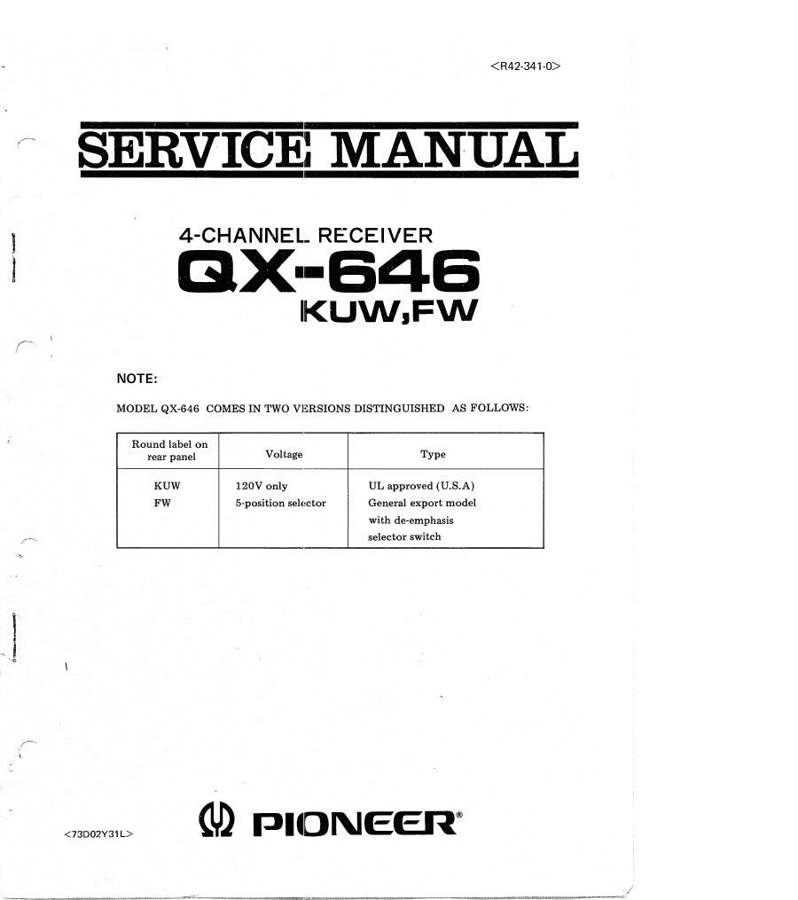
pioneer gx 646 service manual

Extracted text from pioneer gx 646 service manual (Ocr-read)


Page 1

SERVICE MANUAL

4-CHANNEL- RECEIVER

3 GX--B4E

|KUW1FW

NOTE:

MODEL QX-646 COMES IN TWO VERSIONS DISTINGUISHED AS FOLLOWS:

Round label on

rear panel Voltage TYPE
KUW 120V only UL approved (U.S.A)
FW 5-position selector General export model

with de-emphasis

selector switch

5

GD PIIDNEEIT

<73D02Y31 L>

Page 2

\
l
snewlv.

10.
11.
12.

OX -84 6

CO NT ENTS
SPECIFICATIONS .......................................... 3
CONNECTION DIAGRAM .................................... 5
FRONT PANEL FACILITIES .................................. 7
BLOCK DIAGRAM ......................................... 9
PARTS AND P.C. BOARD LOCATION
5.1 Top View ........................................... 11
5.2 Bottom View ......................................... 1 2
DISASSEMBLY ........................................... 13
SIGNAL PATH AND CIRCUIT FUNCTIONS
7.1 Recording and Playback of 00-4 Discs ....................... 14
7.2 1/2 Equalizer .......................................... 15
7.3 2/2 Equalizer ......................................... 16
7.4 Low Pass Filter ........................................ 15
7.5 AF Amplifier Assembly .................................. 16
7.6 High Pass Filter ........................................ 16
7.7 Phase Locked Loop FM Detector ............................ 16
7.8 Automatic Selectivity Control .............................. 17
7.9 Sub Equalizer ......................................... 17
7.10 Low Pass Filter ........................................ 17
7.11 Automatic Noise Reduction System .......................... 17
7.1 2 Phase Splitter ......................................... 13
7.13 Separation Control Circuit ................................ 13
7.14 Matrix Circuit .* ........................................ 18
7.15 Muting Circuit ........................................ 13
ALIGNMENT PROCEDURE
8.1 FM/AM IF Alignment ................................... 19
8.2 FM/AM Tracking Alignment ............................... 20
8.3 MPX Decoder Alignment ................................. 20
8.4 Other Alignments ...................................... 21
8.5 Adjustment of Phase Locked Loop Oscillation Frequency ............ 22
8.6 Carrier Level Adjustment ................................. 22
DIAL CORD STRINGING .................................... 23
LEVEL DIAGRAM ......................................... 24
EXPLODED VIEW AND PARTS LIST .............................. 25
SCHEMATIC DIAGRAMS, P.C. BOARD PATTERNS AND PARTS LISTS
12.1 Circuit Connection Diagram and Miscellaneous Parts --------------- 29
12.2 Tuner Assembly (AWE-003) ............................... 33
12.3 Equalizer and Matrix Circuit Assembly (AWM-045) -------------- 40
12.4 Sub Channel Circuit Assembly (AWX-051) ---------------------- 46
12.5 Decoder Circuit Assembly (AWM-031) ------------------------ 56
12.6 Control Amplifier Assembly (AWG-O15) ------------------------ 61