Pioneer gmx 502 service manual

This is the 19 pages manual for pioneer gmx 502 service manual.
Read or download the pdf for free. If you want to contribute, please upload pdfs to audioservicemanuals.wetransfer.com.

Page: 1 / 19
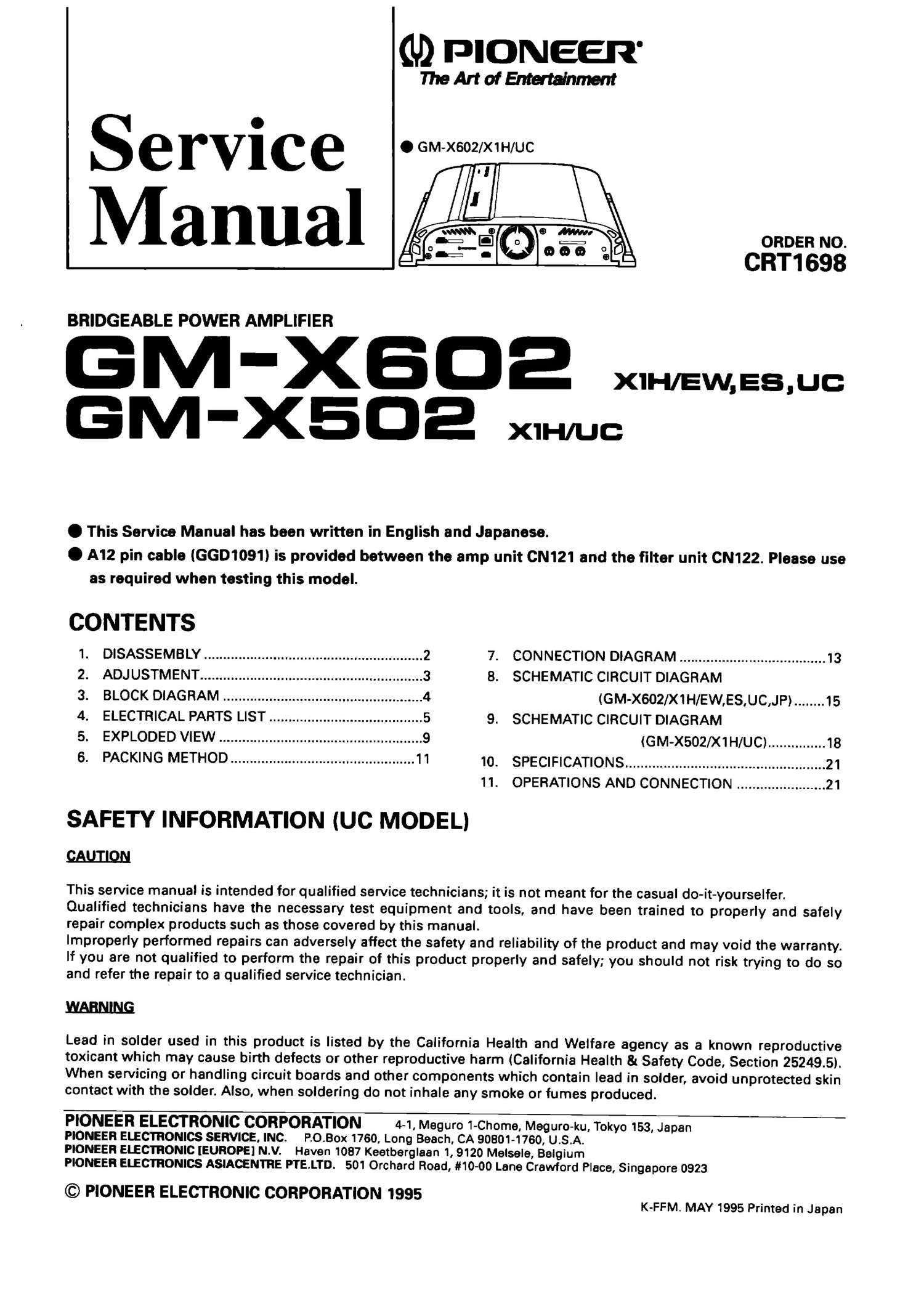
pioneer gmx 502 service manual

Extracted text from pioneer gmx 502 service manual (Ocr-read)


Page 1

(U) PIONEER

flieArtofEntertdnmem

Service .W,

ORDER NO

ch1693'

BRIDGEABLE POWER AMPLIFIER

M 'Xfla x.H,Ew,Es,uc
GM'XE-E x1H/uc:

O This Service Manual has been written in English and Japanese.

0 A12 pin cable (GGD1091) is provided between the amp unit CN121 and the filter unit CN122. Please use
as required when testing this model.

CONTENTS
1. DISASSEMBLY ......................................................... 2 7. CONNECTION DIAGRAM ...................................... 13
2 ADJUSTMENT .......................................................... 3 8. SCHEMATIC CIRCUIT DIAGRAM
3. BLOCK DIAGRAM .................................................... 4 (GM-X60200H/EW,ES,UC,JP) ........ 15
4. ELECTRICAL PARTS LIST ........................................ 5 9. SCHEMATIC CIRCUIT DIAGRAM
5 EXPLODED VIEW ..................................................... 9 (G m-x502/x1 H/UC) ............... 13
6 PACKING METHOD ................................................ 11 10. SPECIFICATIONS .................................................... 21
11. OPERATIONS AND CONNECTION ....................... 21
SAFETY INFORMATION IUC MODEL)
QAIJIIQN

This service manual is intended for qualified service technicians; it is not meant for the casual do-it-yourselfer.
Qualified technicians have the necessary test equipment and tools, and have been trained to properly and safely
repair complex products such as those covered by this manual.

Improperly performed repairs can adversely affect the safety and reliability of the product and may void the warranty.

If you are not qualified to perform the repair of this product properly and safely; you should not risk trying to do so
and refer the repair to a qualified service technician.

EARNING

Lead in solder used in this product is listed by the California Health and Welfare agency as a known reproductive
toxicant which may cause birth defects or other reproductive harm (California Health & Safety Code, Section 25249.5).
When servicing or handling circuit boards and other components which contain lead in solder, avoid unprotected skin
contact with the solder. Also, when soldering do not inhale any smoke or fumes produced.

PIONEER ELECTRONIC CORPORATION 4-1, Meguro 1-Chome, Meguro-ku, Tokyo 153, Japan
PIONEER ELECTRONICS SERVICE. INC. ROBOX 1760, Long BBBCI'I. CA 90801-1760, U.S.A.
PIONEER ELECTRONIC [EUROPE] N.V. Haven 1037 Keetberglaan 1, 9120 MOISBIB, Belgium

PIONEER ELECTRONICS ASIAOENTRE PTE.LTD. 501 Orchard Road, #10-00 Lane Crawford Place, Singapore 0923
© PIONEER ELECTRONIC CORPORATION 1995

K-FFM. MAY 1995 Printed in Japan

Page 2

GM-XBDE,X502

1. DISASSEMBLY / fifigo) b 70 7*:

. Removing the Case
1.Remove the four screws A, and then remove the case.

. 7-20Nif bbfl:
1.11-2AE42ki1fb'C. r-xéiifh

Fig.1

. Removing the Amp Unit
1. Remove the two screws B. and then remove the amp unit. B

.7P7ll-y HDii'szirt
1.??8E2Nifb. 771/7127 remain

Fig.2