Pioneer gma 5040 service manual

This is the 16 pages manual for pioneer gma 5040 service manual.
Read or download the pdf for free. If you want to contribute, please upload pdfs to audioservicemanuals.wetransfer.com.

Page: 1 / 16
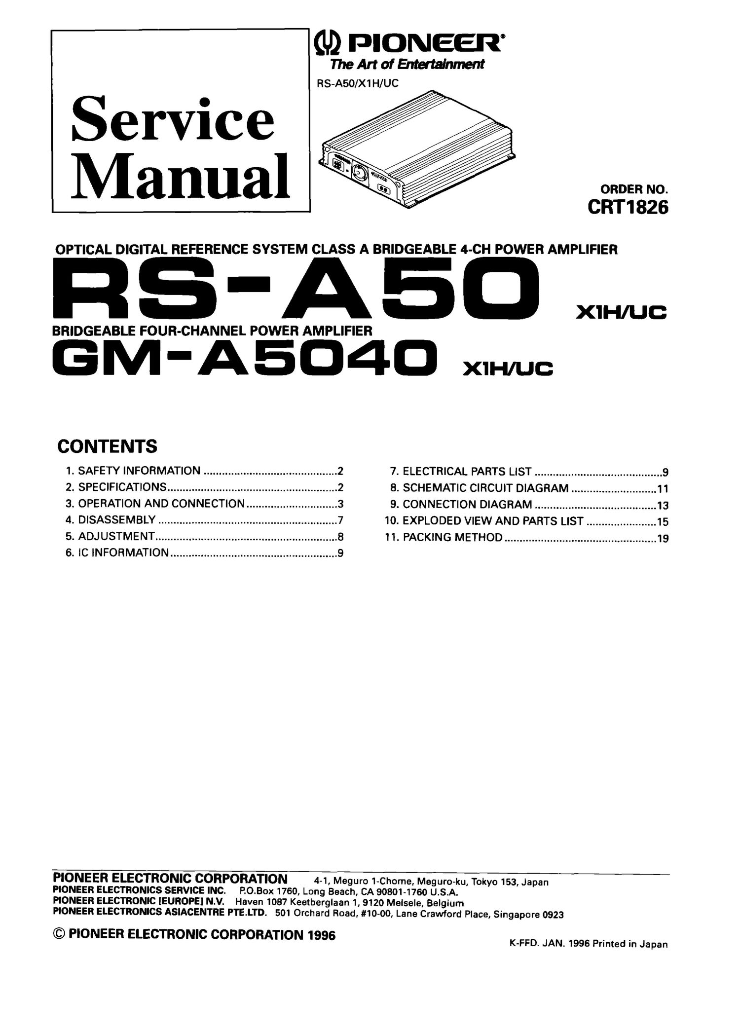
pioneer gma 5040 service manual

Extracted text from pioneer gma 5040 service manual (Ocr-read)


Page 1

(U) PIONEER
The Art of Entertainment
RS-ASO/X1H/UC

ORDER NO.

CRT1826

OPTICAL DIGITAL REFERENCE SYSTEM CLASS A BRIDGEABLE 4-CH POWER AMPLIFIER

- -
RS A5. W

BRIDGEABLE FOUR-CHANNEL POWER AMPLIFIER

GM-A504O xu-uuc

CONTENTS
1. SAFETY INFORMATION ............................................ 2 7. ELECTRICAL PARTS LIST .......................................... 9
2. SPECIFICATIONS ........................................................ 2 8. SCHEMATIC CIRCUIT DIAGRAM ............................ 11
3. OPERATION AND CONNECTION .............................. 3 9. CONNECTION DIAGRAM ........................................ 13
4. DISASSEMBLY ........................................................... 7 10. EXPLODED VIEW AND PARTS LIST ....................... 15
5. ADJUSTMENT ............................................................ 8 11. PACKING METHOD .................................................. 19
6. IC INFORMATION ....................................................... 9

PIONEER ELECTRONIC CORPORATION 4-1, Meguro 1-Chome, Meguro-ku, Tokyo 153, Japan
PIONEER ELECTRONICS SERVICE INC. P.O.Box 1760, Long Beach, CA 90801-1760 USA.

PIONEER ELECTRONIC [EUROPE] N.V. Haven 1087 Keetberglaan 1, 9120 Melsele, Belgium

PIONEER ELECTRONICS ASIACENTRE PTE.LTD. 501 Orchard Road, #10-00, Lane Crawford Place, Singapore 0923

© PIONEER ELECTRONIC CORPORATION 1996 K-FFD. J AN. 1995 printed in Japan

Page 2

HS-ASO,GM-A504O

1. SAFETY INFORMATION
cAuriou

This service manual is intended for qualified service technicians; it is not meant for the casual do-it-yourselfer.

Qualified technicians have the necessary test equipment and tools, and have been trained to properly and safely repair
complex products such as those covered by this manual.

Improperly performed repairs can adversely affect the safety and reliability of the product and may void the warranty.
If you are not qualified to perform the repair of this product properly and safely: you should not risk trying to do so and

refer the repair to a qualified service technician.

m

Lead in solder used in this product is listed by the California Health and Welfare agency as a known reproductive
toxicant which may cause birth defects or other reproductive harm (California Health 81 Safety Code. Section 25249.5).
When servicing or handling circuit boards and other components which contain lead in solder, avoid unprotected skin

contact with the solder. Also, when soldering do not inhale any smoke or fumes produced.

2. SPECIFICATIONS

Power source .................. 14.4 V DC (10.8 - 15.6 V allowable)
Grounding system ...................................... Negative type
Current consumption ................ 38 A (4 (2 Continuous power)
1.5 A (4 Q, No signal)

Average current consumption* ............. 10 A (4 Q, 4 channels)
17 A (4 Q, 2 channels)

Fuse .................... - ........................... Main unit:20Ax2
Dimensions ......................... 250 (W) x 57.5 (H) x 310 (D) mm
[9-7/8 (W) x 2-1/4 (H) x 12-1/4 (D) in.|

Weight ................................................. 4.7 kg (10.3 lbs.)
Maximum power output ...................... 100 W x 4/300 W x 2

300Wx1+100Wx2
Continuous power output
............ 50 W x 4 (at 14.4 V, 4 Q, 20 Hz - 20 KHz, 0.04% THD)
150 W x 2 (at 14.4 V, 4 Q, 20 Hz - 20 KHz, 0.4% THD)
75 W x 4 (at 14.4 V, 2 Q, 20 Hz - 20 KHz, 0.4% THD)
50 W x 4 (at 12 V, 4 Q, 20 Hz - 20 KHz, 0.04% THD)
120 W x 2 (at 12 V, 4 Q, 20 Hz - 20 KHz, 0.4% THD)
60 W x 4 (at 12 V, 2 Q, 20 Hz - 20 KHz, 0.4% THD)

Frequency response ...................... 7 - 35 kHz (+0 dB, -1 dB)
Distortion ....................................... 0.0015% (10 W, 1 kHz)
Signal-to-noise ratio .......... . ............ 106 dB (lHF - A network)
Load impedance ............................. 4 Q (2 - 8 Q allowable)
Slew Bate40 V/usec.
Separation ................................................ 75 dB (1 kHz)
Damping factor ..................................................... 140
Headroom margin ................................................. 0 dB
Input level / impedance ....... - ...................... 0.4 - 2 V/22 I<.Q

Note:
Specifications and the design are subject to possible modification
without notice due to improvements.

Average current d'awn

The average current drawn is nearly the maximum current drawn
by this unit when an audio signal is input. Use this value when
working out total current drawn by multiple power amplifiers.