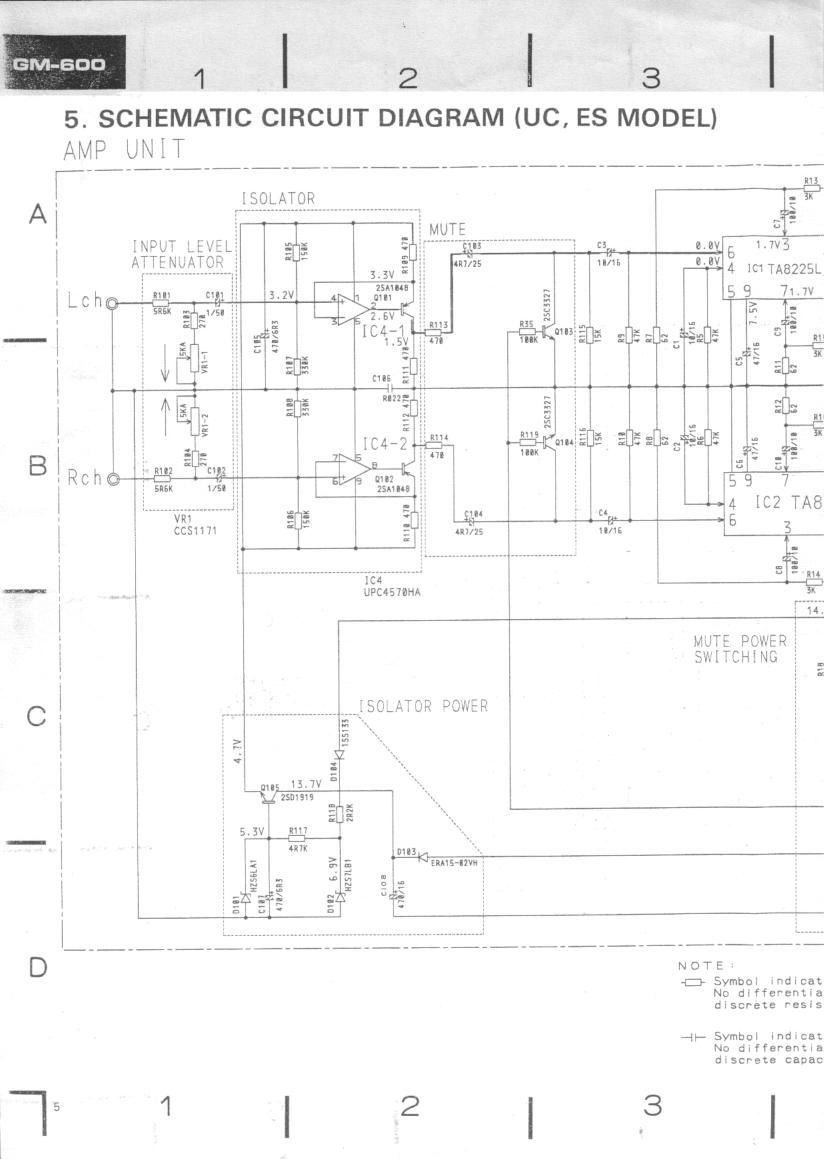
Pioneer gm 600 schematic
This is the 2 pages manual for pioneer gm 600 schematic.
Read or download the pdf for free. If you want to contribute, please upload pdfs to audioservicemanuals.wetransfer.com.
Extracted text from pioneer gm 600 schematic (Ocr-read)
Page 2
- ' _ -POM-R ' - ' ' ' 'fi 7.5V
1: .% g E AMP 8 _G L-
: s = 5 . I E 5].
36 1.1v3 15113 1017 3
0,9 13.7V 5 '3 4.;
4 1C1TA8225L13'7V I~- 2i" 51:":
'59 7m 1211 1413 a 3'3; ° ° 7
:3: $5303 I; 3 ' mi: ®_D H
u mi: 9 =
D . E ' 8.3V
¢ a? @ @ GND
: a m :
- I = . V
m ~=i5=UE : 3 :r E =T" 75
°' 1%-; .515 ° QED-Chm
bus; "7 1211 1413
4 m TA8225L 1 .- 5: _::§
'6 3 1516 11017 ° °
3 = m g : it 1.5V
3? , (ED-1:3 R-
""" 14,4v
14.4v 15mm @4 W ACC
MUTE POWER; 2 g 7.5A
SWITCHING : .1- -: 52g
3 5": > H SYSTEM
2 Q) '"(j CONTROL
1 II J TERMINAL
;8 wnftzf > 3 -C1
§~-~MLnr~m::::E i g P
I T I T I S E
3
E 2515mm
_ _ _ _ _ _ _ _ _ _ _ _ l
N O'T E
{2} Symbol indicates a resistor.
No differentiation Is made between chip reslstors and
dlscrete resistors.
-n- Symbol indicates a capacitor.
No differentiation is made between chip capacltors and
discrete capacitors.
4 T5
Decimal points for resistor
and capacitor fixed values
are expressed as:
2 . 2-2R2
0 . @22-4R022
Fm.5