Pioneer drm 1804 x service manual

This is the 53 pages manual for pioneer drm 1804 x service manual.
Read or download the pdf for free. If you want to contribute, please upload pdfs to audioservicemanuals.wetransfer.com.

Page: 1 / 53
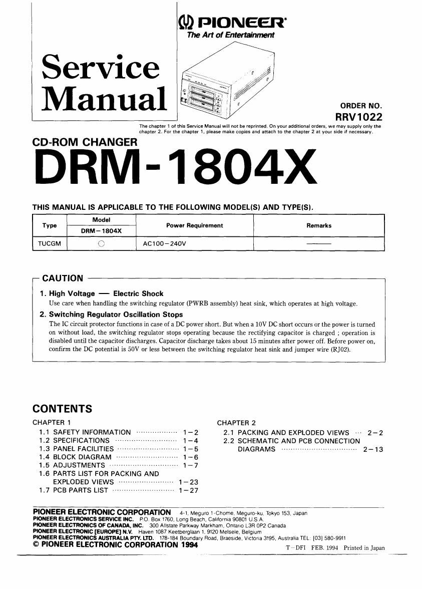
pioneer drm 1804 x service manual

Extracted text from pioneer drm 1804 x service manual (Ocr-read)


Page 1

i (L9 PIONEER

The Art of Enterminmen!

Service
Manual am;

The chapter I 01 this Service Manual will not be reprinted, On your additional orders, we may supply only the
chapter 2. For the chapter 1, please make copies and attach to the chapter 2 at your side if necessary.

CD-ROM CHANGER

DRM-1804X

THIS MANUAL IS APPLICABLE TO THE FOLLOWING MODELiS) AND TYPEISI.

Model
Type - Power Requirement Remarks
DRM - 1 804X
TUCGM C AC100-240V -

CAUTION

1. High Voltage - Electric Shock
Use care when handling the switching regulator (PWRB assembly) heat sink, which operates at high voltage.

2. Switching Regulator Oscillation Stops
The IC Circuit protector functions in case of a DC power short But when a 10V DC short occurs or the power is turned
on without load, the switching regulator stops operating because the rectifying capacitor is charged ; operation is
disabled until the capacitor discharges. Capacitor discharge takes about 15 minutes after power off. Before power on,
confirm the DC potential is 50V or less between the switching regulator heat Sink and jumper wire (R102).

CONTENTS
CHAPTER 1 CHAPTER 2
1.1 SAFETY INFORMATION -- -- 1-2 2.1 PACKING AND EXPLODED VIEWS 2-2
1.2 SPECIFICATIONS ------- - 1-4 2.2 SCHEMATIC AND PCB CONNECTION
1.3 PANEL FACILITIES 1 -- 1-5 DIAGRAMS --------------------------------- 2-13
1.4 BLOCK DIAGRAM . -- - 1-6
1.5 ADJUSTMENTS ----------------------------- 1-7
1.6 PARTS LIST FOR PACKING AND
EXPLODED VIEWS ------------------------ 1-23
1.7 PCB PARTS LIST --------------------------- 1-27

PIONEER ELECTRONIC CORPORATION 4-1. Meguro i-Chome, Meguro-ku. Tokyo 153, Japan

PIONEER ELECTRONICS SERVICE INC. PO. Box 1760, Long Beach. Camomia 90801 USA.

PIONEER ELECTRONICS OF CANADA, INC. 300 Ailstate Parkway Markham, Ontario L3R 0P2 Canada

PIONEER ELECTRONIC [EUROPE] N.V. Haven 1087 Keetberglaan 1. 9120 Melsele. Belgium

PIONEER ELECTRONICS AUSTRALIA PTY. LTD. 178-184 Boundary Road. Braesxde, Victoria 3195. Auslralla TEL [03] 580-9911

© PIONEER ELECTRONIC CORPORATION 1994 TSDFI FEB. 1994 Printed in Japan

Page 2

DRM- 1 804x

CHAPTER 1
1.1 SAFETY INFORMATION

This service manual is intended for qualified service technicians; It Is not meant for the casual
do-it-yourselfer. Qualified technicians have the necessary test equipment and tools, and have been
trained to properly and safely repair complex products such as those covered by this manual.

improperly performed repairs can adversely affect the safety and reliability of the product and may void
the warranty. If you are not qualified to perform the repair of this product properly and safely, you should

not risk trying to do so and refer the repair to a qualified service technician.

WARNING

Lead in solder used in this product is listed by the California Health and Welfare agency as a known reproductive toxicant which
may cause birth defects or other reproductive harm (California Health 8r Safety Code, Section 252495).

When servicing or handling circuit boards and other componenta which contain lead in solder. avoid unprotected akin contact with
the solder. Alao, when soldering do not inhale any smoke or fumes produced.

NOTICE
(FOR CANADIAN MODEL ONLY)

Fuse symbols lEEl- (fast operating fuse) and/or a (slow operating fuse) on PCB indicate that replacement parts

must be of identical designation.

REMARQUE
(POUFI MODELE CANADIEN SEULEMENT)

Les symboles de fusible EEI (fusible de type rapide) et/ou a (fusible de type lent) sur CCi indiquent que les

pieces de remplacement doivent avoir la meme designation.

FIFOR USA MODEL ONLY)

1.5AFETY PRECAUTIONS

The following check should be performed for the
continued protection of the customer and service
technician.

LEAKAGE CURRENT CHECK

Measure leakage current to a known earth ground
lwater pipe, condurt, etc.) by connecting a leakage
current tester such as Simpson Model 2292 or

metal parts of the appliance (input/output terminals.
screwheads, metal overlays, control shaft, etc). Plug
the AC line cord of the appliance directly into a 120V
AC GOHZ outlet and turn the AC power switch on. Any
current measured must not exceed 3.5mA

CM-
Leaiage

current
tester

Reading should
not be above
3.5mA

Test all
exposed metal
surfaces

Also test wrth
plug reversed
(Using AC adapter
plug as requiredl

Earth
ground

AC Leakage Test

equivalent between the earth ground and all exposed.

ANY MEASUREMENTS NOT WITHIN THE LIMITS
OUTLINED ABOVE ARE INDICATIVE OF A P0-
TENTIAL SHOCK HAZARD AND MUST BE COR-
RECTED BEFORE RETURNING THE APPLIANCE TO
THE CUSTOMER.

2. PRODUCT SAFETY NOTICE

Many electrical and mechanical parts In the appli-
ance have special safety related characteristics. These
are often not evident from visual inspection nor the
protection afforded by them necessarily can be ob
tained by using replacement components rated for vol.
tage, wattage, etc. Replacement parts which have
these special safety characteristics are identified in
this Service Manual.

Electrical components having such features are

identified by marking with a A on the schematics and
on the parts list in this Service Manual.
The use of a substitute replacement component which
dose not have the same safety characteristics as the
PlONEEFl recommended replacement one, shown in
the parts list in this Service Manual, may create shock,
fire, or other hazards.

Product Safety is continuously under review and
new instructions are issued from time to time. For
the latest information, always consult the current
PlONEER Service Manual. A subscription to, or ad
ditional copies of, PIONEER Service Manual may be
obtained at a nominal charge from PIONEER.