Pioneer cx 7000 owners manual

This is the 24 pages manual for pioneer cx 7000 owners manual.
Read or download the pdf for free. If you want to contribute, please upload pdfs to audioservicemanuals.wetransfer.com.

Page: 1 / 24
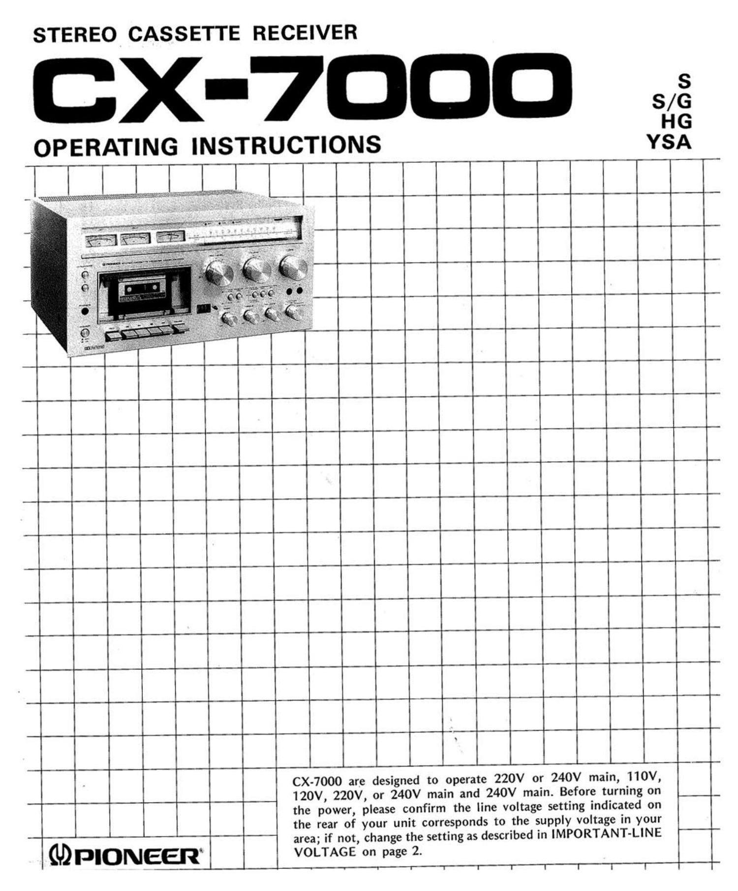
pioneer cx 7000 owners manual

Extracted text from pioneer cx 7000 owners manual (Ocr-read)


Page 1

STEREO CASSETTE RECEIVER

X-7-I-

HG
OPERATING INSTRUCTIONS YSA

... -.~,
' 'mfitxawo

I WI I I IMI _

CX-7000 are designed to operate 220V or 240V main, 110V,
120V, 220V, or 240V main and 240V main. Before turning on

the power, please confirm the line voltage setting indicated on
the rear of your unit corresponds to the supply voltage in your

area; if not, change the setting as described in IMPORTANT-LINE

wpIONEEl VOLTAGE on page 2.

a I v i f I I I I I

Page 2

CONTENTS

Important - Line Voltage ............. 2 Front Panel Facilities ................. 12
Features ........................... 3 (Cassette Deck Section)
Stereo System Composition ............ 4 Basic Operation ..................... 13
Installation Cautions ................. 4 Cassette Tapes ...................... 14
Connection Diagram .................. 5 Playback ........................... _ 1 5
Antenna and Ground Connections ....... 6 Recording .......................... 16
Connections ........................ 7 Using the MIC Jacks .................. 17
Front Panel Facilities ............ . ..... 8 Using the *Dolby System .............. 18
(Receiver Section) Using the TAPE Jacks ................ 19
Before Operation .................... 10 Conditions Frequently Mistaken for _
Listening to Broadcasts ............... 10 Malfunctions ..................... 20
Listening to Records ................. 10 Specifications ....................... 22
Using the AUX 11113111? Jacks ............ 11 Maintenance . . . . . . . 2 ................ 24
Schematic Diagram .............. Insertion

IMPORTANT-LINE VOLTAGE

These operating instructions pertain to 220V - 240V selectable (HG) models, 110V - 120V - 220V - 240V
selectable (S) models and 240V only (YSA) models. The LINE VOLTAGE SELECTOR switch has been set
according to the local AC power line supply in the area of use. YSA models do not have the LINE
VOLTAGE SELECTOR switch. Before operating your unit, be sure to confirm that this switch has been
set properly. If it is necessary to change the switch setting, do so according to the steps below.

, S MODELS (110V-120V-220V-240V)

1. Disconnect the AC mains cord.

2. Use the Phillips screwdriver to unscrew the fuse
cap, then take out the fuse and SELECTOR plug
(Fig. 1).

3. Reinstall the SELECTOR plug so that its cut-out
section exposes the voltage indication of the
SELECTOR socket which corresponds to your
household AC power.

4. Refer to the table and install a replacement fuse
(provided as accessory).

5. Insert fuse in fuse cap, then install cap to plug
and tighten.

HG MODELS (220V-240V)

1. Disconnect the AC mains cord.

2. Use the Phillips screwdriver to loosen the
mounting screw, then remove the SELECTOR
plug (See Fig. 2).

3. Reinstall the SELECTOR plug with its cut-out
section exposing the correct voltage indication.

4. Insert and tighten the mounting screw.

FOR YOUR SAFETY

1. Insert this plug only into effectively earthed
three-pin plug-socket outlet.

2. If any doubt exists regarding the earthing, con-

' sult a qualified electrician.

3. Extension cords, if used, must be three-core
correctly wired.

S model

VOLTAGE FUSE
1 10V. 120V 4A
220VJ 240V 2A

HG model

Phillips

, s.
screwdriver
% Selector

Screw 9'09

2 *Manufactured under license from Dolby Laboratories Incorporated.
*Dolby and DE] are trademarks of Dolby Laboratories Incorporated.