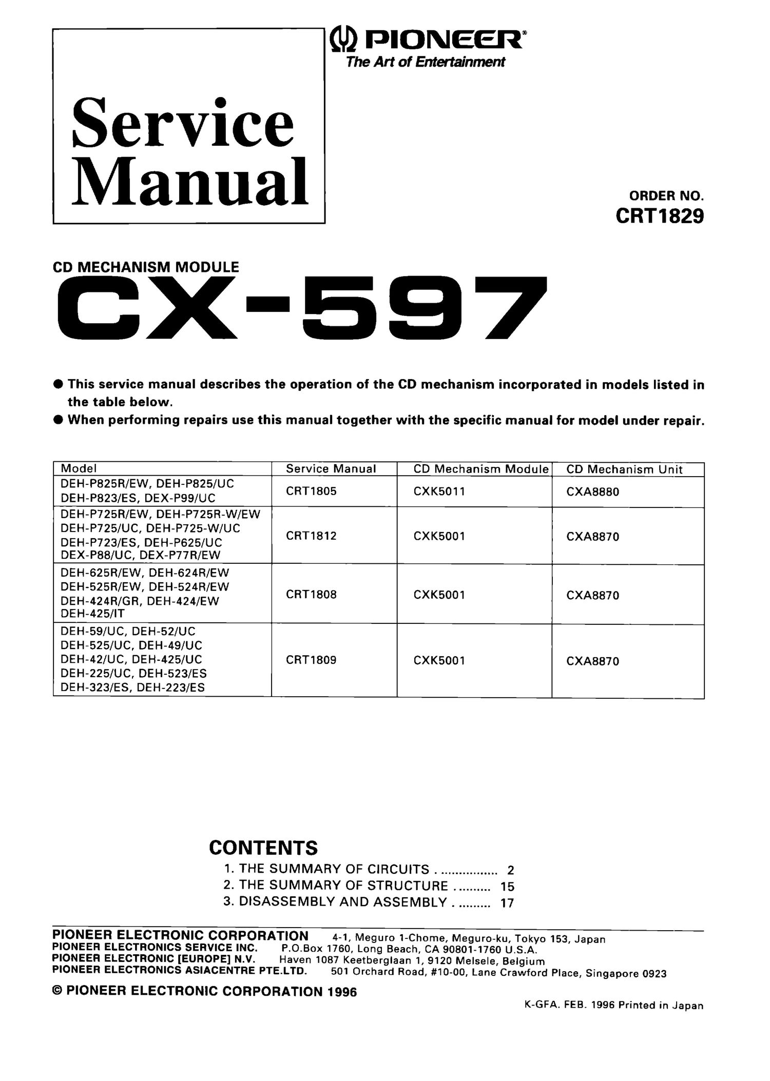
Pioneer cx 597 service manual
This is the 20 pages manual for pioneer cx 597 service manual.
Read or download the pdf for free. If you want to contribute, please upload pdfs to audioservicemanuals.wetransfer.com.
Extracted text from pioneer cx 597 service manual (Ocr-read)
Page 1
GD PIONEER
The Art of Entertainment
Service
Manual
CD MECHANISM MODULE
CX-557
ORDER NO.
CRT1829
O This service manual describes the operation of the CD mechanism incorporated in models listed in
the table below.
0 When performing repairs use this manual together with the specific manual for model under repair.
'-
Model Service Manual CD Mechanism Module? CD Mechanism Unit
DEH-P825R/EW, DEH-P825/UC
DEH-P823/ES, DEX_P99/UC CRT1805 CXK5011 CXA8880
rDEH-P725R/EW, DEH-P725R-W/EW 1 I
DEH-P725/UC, DEH-P725-W/UC
DEH-P723/ES, DEH-P625/UC CRT1812 CXK5001 CXA8870
_ DEX-P88/UC, DEX-P77R/EW
DEH-625R/EW. DEH-624R/EW
DEH-525R/EW, DEH-524R/EW
DEH-424R/GR, DEH-424/EW CRT1808 CXK5001 CXA8870
DEH-425/IT
DEH-59/UC, DEH-52/UC
DEH-525/UC, DEH-49/UC
DEH-42/UC, DEH-425/UC CRT1809 CXK5001 CXABB'IO
DEH-225/UC, DEH-523/ES
DEH-323/ES, DEH-223/ES
CONTENTS
1. THE SUMMARY OF CIRCUITS. ................ 2
2. THE SUMMARY OF STRUCTURE. ......... 15
3. DISASSEMBLY AND ASSEMBLY. ......... 17
PIONEER ELECTRONIC CORPORATION
PIONEER ELECTRONICS SERVICE INC.
PIONEER ELECTRONIC [EUROPE] N.V.
PIONEER ELECTRONICS ASIACENTRE PTE.LTD.
© PIONEER ELECTRONIC CORPORATION 1996
4-1, Meguro 1-Chome, Meguro-ku, Tokyo 153, Japan
P.O.Box 1760, Long Beach, CA 90801-1760 U.S.A.
Haven 1087 Keetberglaan 1, 9120 Melsele, Belgium
501 Orchard Road, #10-00, Lane Crawford Place, Singapore 0923
K-GFA. FEB. 1996 Printed in Japan
Page 2
(BX-597
1. THE SUMMARY OF CIRCUITS
1.1 PRE-AMP SECTION IUPC2572GS:
IC101I
This section processes the pickup output signals to
create the signals for the servo, demodulator & con-
trol.
The pickup output signals are I-V converted by the
pre-amp with built in photo-detector in the pickup,
and added by the RF amp CNN to obtain the RF, FE,
TE, TE zero cross, and other signals.
The main component is the UPCZ572GS and each
section is explained below. Because this system has
a single power supply (+5V). the reference voltage
for this lC, the PU and the servo circuit is the voltage
REFO (+2.5V). The HEFO signal is obtained by buffering
REFOUT from the servo LSI (|C201: UPD63702GF) and
is available from Pin 19 of |C101. All measurements
should be done using this REFO as reference.
Note: During measurement, do not short REFO and
GND.
1) APC Circuit (Automatic Power Control)
When the laser diode is driven with constant current,
the optical output has large negative temperature
characteristics. So the current must be controlled to
hold the output constant with the monitor diode. The
circuit that carries out this function is the APC circuit.
The LD current is obtained by measuring the voltage
between LD1 and ground and the value of this cur-
rent is about 35mA.
EFM-IN 1
AGC-OUT 9
c A60 9
RF-IN 4
ENVELOPE
"F HPF
AGC 1
i l
DETECT
RF-OUT e
C1.3T 7
1
RF- 9- "
C2.3T B
€31 EFM-OUT
€5- C.DEF
DEFECT
DC SHIFT
9
®
0*
GD
GB
GD
0
IQ __ 3:- DC SHIFT
MIRROR
CIRCUIT
3»
L 3T DETECT
PHASE DETECT
~+ pa
_ FE BAL ,
120m 6) CIT-OUT
gig) C.FE
@i FE-OUT
Br
CONTROL
C
ONTROL
}
.3.
Vcc
2;, FE-
Qn GND
TE-
q, TE-OUT1
B} @ TE-OUT2
Vcc
A
C
B
a"? ~+
. .2- >
E
PD
LD
APC
LDON IE
VREF-OUT ®
4
2 J DET-IN
. 1 DET-OUT
Q) VFIEF-IN
Fig.1 : UPC2572GS BLOCK DIAGRAM
PU UNIT
VCELSV)
.5 l
51.24.
0.1uFl J C101
0-0
L01 R101 (100pF/6.3VI
1052
R102
IZQ 5V
Fig.2 :
C1102 UMDZN
UPC2572
APC CIRCUIT