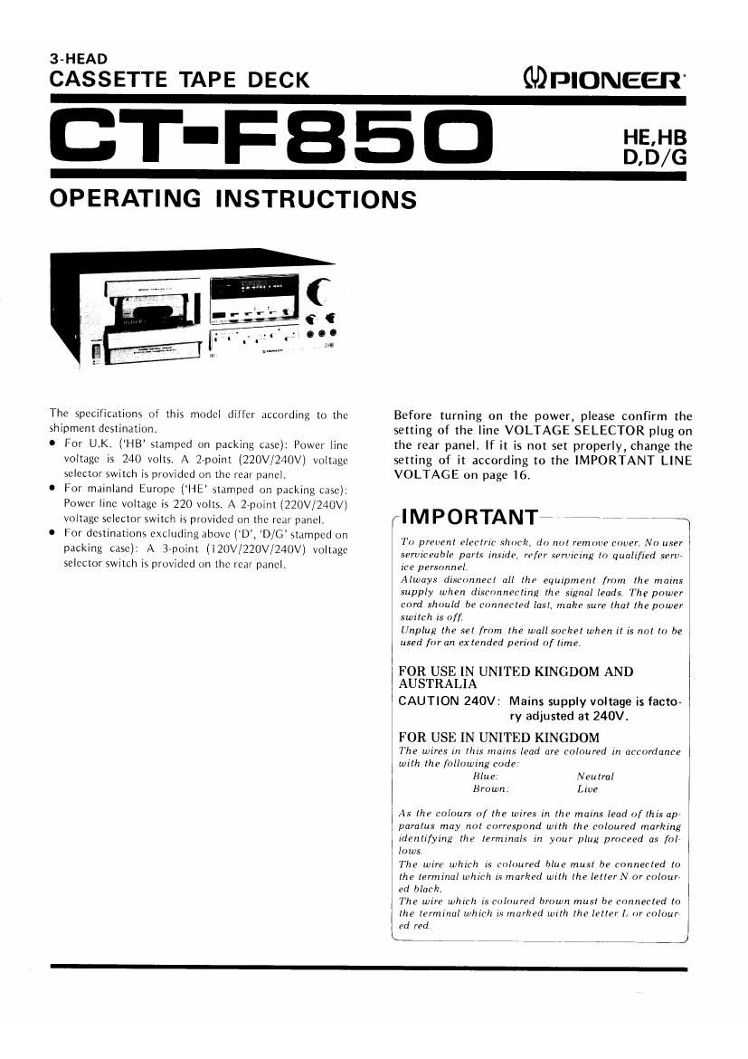
Pioneer ctf 850 owners manual
This is the 18 pages manual for pioneer ctf 850 owners manual.
Read or download the pdf for free. If you want to contribute, please upload pdfs to audioservicemanuals.wetransfer.com.
Extracted text from pioneer ctf 850 owners manual (Ocr-read)
Page 1
3-HEAD
CASSETTE TAPE DECK
GDPIONEER-
OPERATING INSTRUCTIONS
The specifications of this model differ according to the
shipment destination.
0 For UK ('HB stamped on packing case); Power line
voltage is 240 volts A 27p0int (220V/240V) voltage
selector switch is provided on the rear panel
0 For mainland Europe (HE stamped on packing case):
Power line voltage is 220 volts. A 2-point (220V/240V)
voltage selector switch is provided on the roar paneii
O For destinations excluding above lD, D/G stamped on
packing case): A 3»point (iElJV/220V/240V) voltage
selector switch is provided on the rear panel.
Before turning on the power, please confirm the
setting of the line VOLTAGE SELECTOR plug on
the rear panel. If it is not set properly, Change the
setting of it according to the IMPORTANT LINE
VOLTAGE on page 16.
(IMPORTANTiefi was
To prevent electric shock, do not remove cover. No user
serviceable parts inside, refer .SfrlIClllg to qualified sertr
icc personnel.
Always disconnect all the equipment from the mains
supply when disconnecting the signal leads, The power
cord should be connected last. make sure lhal the power
switch is of[
Unplug the set from the wall socket when it is not to be
used for an extended period of time,
FOR USE IN UNITED KINGDOM AND
AUSTRALIA
CAUTION 240V: Mains supply voltage is facto~
ry adjusted at 240V.
FOR USE IN UNITED KINGDOM
The wires in this mains lead are coloured in accordance
with the following code
Blue: Neutral
Brown: Live
As the colours of the wires in the mains lead o/lhis apr
paratus may not correspond with the coloured marking
identifying the terminals in your plug proceed as fol
lows
The wire which is coloured blue must be connected to
the terminal which is marked with the letter N or colour-
ed black.
The wire which is coloured brown must be connected to
the terminal which is marked with the letter I, or colour
ed red,
O _ ,J
W
Page 2
CONTENTS
Features ................ 2 Playback ................ 11 Troubleshooting ..... Insertion
Precautions .......... 3 Operations with the Timer . . 12 Schematic Diagram . . . Insertion
Front Panel Facilities ...... 4 Maintenance ............. 12 Table of Leading Brands of Tapes
Connections . . . . . ........ 6 The Dolby NR System ..... 13 ..... Insertion
Basic Operations . . . ....... 7 Cassette Tapes ............ 14
Recording ............... 8 Specifications ............ 15
Microphone Recording ..... 10 Important-Line Voltage . . . . 16
FEATURES
Transport Section Engineered for Stable Tape Run
This deck features the closed loop dual capstan system whereby
a capstan is stationed on either side of the heads. This system
maintains a stable contact between the heads and the tape so that
the tape travels at a constant tension all the time, and it also helps
to suppress dropouts in the tape and fluctuations in the level.
Another important point is that external vibration transmitted from
the reel bases and tape guides to the tape is kept down to the
minimum for a marked reduction in the modulation noise and both
recording and playback which are faithful to the original sound.
The DC servo motor which provides a stable rotational speed is
combined with the ultra-precision-engineered capstans and good
dynamic balance flywheels to yield a truly superior tape transport
performance, and a great improvement in the wow and flutter
characteristics.
Yet another prime feature is the mechanical governor motor
with its powerful rotation torque and less ripple. This Is used for
the takc»up operations, and enables reliable fast forward and
rewind operations.
Three-Head System with Recording/Playback
Combination Head
This deck adopts a recording head and a playback head which
are combined to fit neatly into a single case as a tidy package. Each
head is made of a sendust core and this makes it possible to exploit
the features of both metal tapes, chrome tapes and ferrichrome
tapes to the full. The heads are provided with a high level of resist-
ance to wear and are tailored to produce tap-notch distortion
characteristics with high input signal levels as well as an excellent
frequency response and signal-to-noise ratio. The contact between
the heads and the tape is surefire and firm and the adhering of dust
and generation of noise caused by magnetization are reduced to the
minimum. These are just a few of the amazing powers of the heads.
What's more, the combination head can be used to monitor a
recording virtually in real time if the playback head is put to work
while you are recording.
Digital Bar Graph Display Level Meter
This dccks level meter features two bar graph fluorescent
display tubes and it functions with all-electronic digital control.
The meter can naturally be used for ordinary VU display and an
added convenience is that it can be used as a peak meter with a fast
response time for detecting pulsing sound accurately. The level
meter mode can be selected in accordance with the program source
which you intend to record, and it facilitates the setting of the
recording level corresponding to the contents of the actual pro-
grams.
2 *Manufactured under license from Dolby Laboratories.
*Dolby and UK] are trademarks of Dolby Laboratories.
Tape Selector and Bias Control to Do Full Justice
to the Performance of Every Kind of Tape
The most is made of not only metal tapes but also chrome tapes,
ferrichrome tapes and standard tapes with the tape selector which
selects the equalizer and bias corresponding to the type of tape
used and also with the bias control which allows the bias of the
tape to be finely adjusted. Adjustments can therefore be made to
suit the characteristics of each type of tape. The bias control can
also be used to produce the frequency response of your preference.
Soft Push-type Tape Mode Selector Switches
Soft push-type electronic controls are adopted in the tape mode
selector mechanism. The deck can be set to rucording playback,
forward, rewind, stop and pause directly iust With a light push on
the switch. There is also a full autovstop mechanism which stops the
tape when the tape is fully wound, and this safeguards the tape
against damage.
Variety of Accessory Mechanisms
Dolby' noise reduction system:
A newly developed low-distortion IC is used for the Dolby NR
system. This serves to reduce greatly the irritating noise heard when
you play back a tape, and it does this without impairing the sound
quality of the original program source. This helps to increase the
dynamic range, and it allows recordings and play back with agood
signal-to-noise ratio.
Output Level Controls with a Clickrstop Position for Easy
Pinpointing of the Reference Playback Level:
The output (playback level) controls can be used to vary the
output level continuously and they are also coupled to the level
meter. This means that it is possible to check the output level on the
meter, regardless of the strength of the recording level. When the
controls are set to their click-stop position, the reierence playback
level can also be checked.
Unattended recording, wake-up playback functions:
If you use the deck along With the optional timer, you can
record the FM broadcasts you do not want to miss while you are
out, and you can also wake yourself up in the morning with play-
back from a program source instead of being rudcly awakened by an
alarm clock buzzer.
Mic plug-coupled input selection:
When the program source Is connected to the MIC iacks, the line
input terminal signal is automatically switched to the microphone
signal.