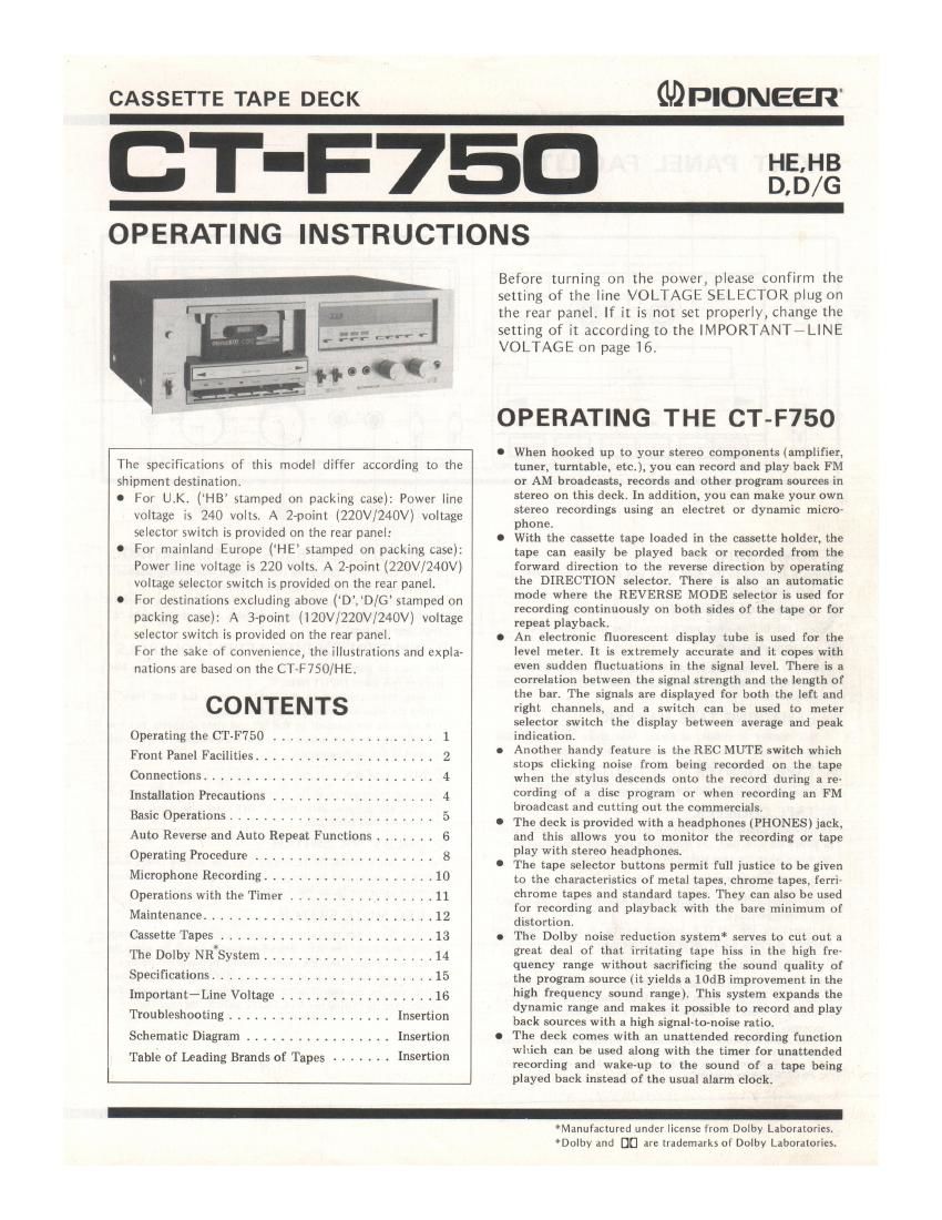
Pioneer ctf 750 owners manual
This is the 16 pages manual for pioneer ctf 750 owners manual.
Read or download the pdf for free. If you want to contribute, please upload pdfs to audioservicemanuals.wetransfer.com.
Extracted text from pioneer ctf 750 owners manual (Ocr-read)
Page 1
CASSETTE TAPE DECK
Gaplomeen'
T-F750 355'}:
OPERATING INSTRUCTIONS
Before turning on the power, please confirm the
setting of the line VOLTAGE SELECTOR plug on
the rear panel. [f it is not set properly, change the
setting of it according to the IMPORTANT-LINE
VOLTAGE on page 16.
1.1.00?
The specifications of this model differ according to the
shipment destination,
0 For UK. (HB stamped on packing case): Power line
voltage is 240 volts. A 2-point (220V/240V) voltage
selector switch is provided on the rear panel:
0 For mainland Europe (HE stamped on packing case):
Power line voltage is 220 volts. A eroint (220V/240V)
voltage selector switch is provided on the rear panel.
I For destinations excluding above (D,D/G' stamped on
packing case): A 3rpoint (lQOV/ZZOV/240V) voltage
selector switch is provided on the rear paneli
For the sake of convenience, the illustrations and expla-
nations are based on the CT-F750/HE,
CONTENTS
Operating the CT-F750 ................... 1
Front Panel Facilities ..................... 2
Connections ........................... 4
Installation Precautions ..... 4
Basic Operations .......... . . 5
Auto Reverse and Auto Repeat Functions ....... 6
Operating Procedure ..................... 8
Microphone Recording .................... 10
Operations with the Timer ................. 11
Maintenance ........................... 12
Cassette Tapes ......................... 13
The Dolby NR*System .................... 14
Specifications ....... . . . ........... 15
Important~Line Voltage . . . . ..... 16
Troubleshooting ................... Insertion
Schematic Diagram ................. Insertion
Table of Leading Brands of Tapes ....... Insertion
OPERATING THE CT-F75O
When hooked up to your stereo components (amplifier,
tuner, turntable, etc.), you can record and play back FM
or AM broadcasts, records and other program sources in
stereo on this deck. In addition. you can make your own
stereo recordings using an electret or dynamic micro-
phone.
With the cassette tape loaded in the cassette holder, the
tape can easily be played back or recorded from the
forward direction to the reverse direction by operating
the DIRECTION selector. There is also an automatic
mode where the REVERSE MODE selector is used for
recording continuously on both sides of the tape or for
repeat playback.
An electronic fluorescent display tube is used for the
level meter. It is extremely accurate and it copes with
even sudden fluctuations in the signal level. There is a
correlation between the signal strength and the length of
the bar, The signals are displayed for both the left and
right channels, and a switch can be used to meter
selector switch the display between average and peak
indication.
Another handy feature is the REC MUTE switch which
stops clicking noise from being recorded on the tape
when the stylus descends onto the record during a re-
cording of a disc program or when recording an FM
broadcast and cutting out the commercials.
The deck is provided with a headphones (PHONES) jack,
and this allows you to monitor the recording or tape
play with stereo headphones
The tape selector buttons permit full justice to be given
to the characteristics of metal tapes, chrome tapes, ferri-
chrome tapes and standard tapes. They can also be used
for recording and playback with the bare minimum of
distortion.
The Dolby noise reduction system* serves to cut out a
great deal of that irritating tape hiss in the high fre-
quency range without sacrificing the sound quality of
the program source (it yields a IOdB improvement in the
high frequency sound range). This system expands the
dynamic range and makes it possible to record and play
back sources with a high signal-to-noise ratio.
The deck comes with an unattended recording function
which can be used along with the timer for unattended
recording and wake-up to the sound of a tape being
played back instead of the usual alarm clock.
*Manufactured under license from Dolby Laboratories.
*Dolby and DCI are trademarks of Dolby Laboratories.
Page 2
-
FRONT PANEL FACILITIES
W
O (D
we mm: a...
c an HT] 2:35..
E. SE
E: W.
ex? some; W: W. sum. W...
L-"_"_ E... E Warts-125$
a t: D E D E :1 E: E
lNFuT ii: now-nor
OWE men MUTE nuuav
unsung»; W L-lMlEH memes
E" « » - per use ewes D a W F
M % E E N m 1
M arm-1mm or so
(D POWER SWITCH
Power is supplied to the deck when this switch is set to ON, and
the level meter lights up.
(D COVER CLOSE BUTTON
Depress this button when you want to close the dust cover.
® DUST COVER
When you are not using the deck, always keep this cover in place
to prevent dust and dirt from adhering to the head section and
rotating parts.
(D REMAINING TAPE MARKER
If this marker is visible, it means that there is enough tape
remaining for several minutes of recording or playback.
@ TAPE COUNTER RESET BUTTON
Depress this button to reset the tape counter display to "000."
© TAPE COUNTER
This indicates how far the tape has traveled. When the tape travels
in a forward direction, the number on the counter increases but it
decreases when the tape travels in the reverse direction.
(D LEVEL METERS
These indicate the input level during recording and the output
level during playback.
By operating the METER selector switch, it can be made to
function as a peak meter, or as an average meter.
HEADPHONE )ACK
This is the output iack for stereo headphones. Plug your head-
phones into this lack when you want to monitor the quality ofa
recording or when you want to listen to a tape privately.
NOTES:
0 Use low-impedance headphones. If you use a high-Impedance
model, you uII'Il not be able to obtain sufficient volume.
O You will damale the microphone if you plug it into the HEAD
PHONEjack by mistake.
E
|
GIB)®®
© OUTPUT (PLAYBACK LEVEL) CONTROL
Use this control to adjust the output signal level during playback.
Turning the control to the right increases the level.
When playing back a reference tape (160 nwb/m), a reference
playback level (MB) is obtained with this control set to the 6
click stop position.
69 INPUT (RECORDING LEVEL) CONTROLS
Use these to adjust the level of the input signals from the MIC
jacks or rear panel INPUT jacks.
Turning these controls to the right increases the level. How to
setting the recording level is detailed on page 9.
The controls are coupled to the left and right channels, but you
can also use them to adjust the right channel (rear) and the left
channel (front) independently.
® MIC JACKS
These are the input jacks for microphone recording. Plug the left
channel microphone into the L Jack and the right channel
microphone into the R jack.
@ DOLBY NR SWITCH
Set this switch to UN for recording with the builtrin Dolby noise
reduction system and for the playback of tapes which have been
recorded using the Dolby NR system.
® REC MUTE SWITCH
Depress this switch to create unrecorded sound blanks on the tape
during recording. The REC MUTE indicator comes on while the
switch is depressed and the tape continues to travel but no signals
are recorded. Also, the level meter indicates the input signal level
which can be monitored with the headphones or speakers. For
details, refer to Using the REC MUTE switch" on page 10.