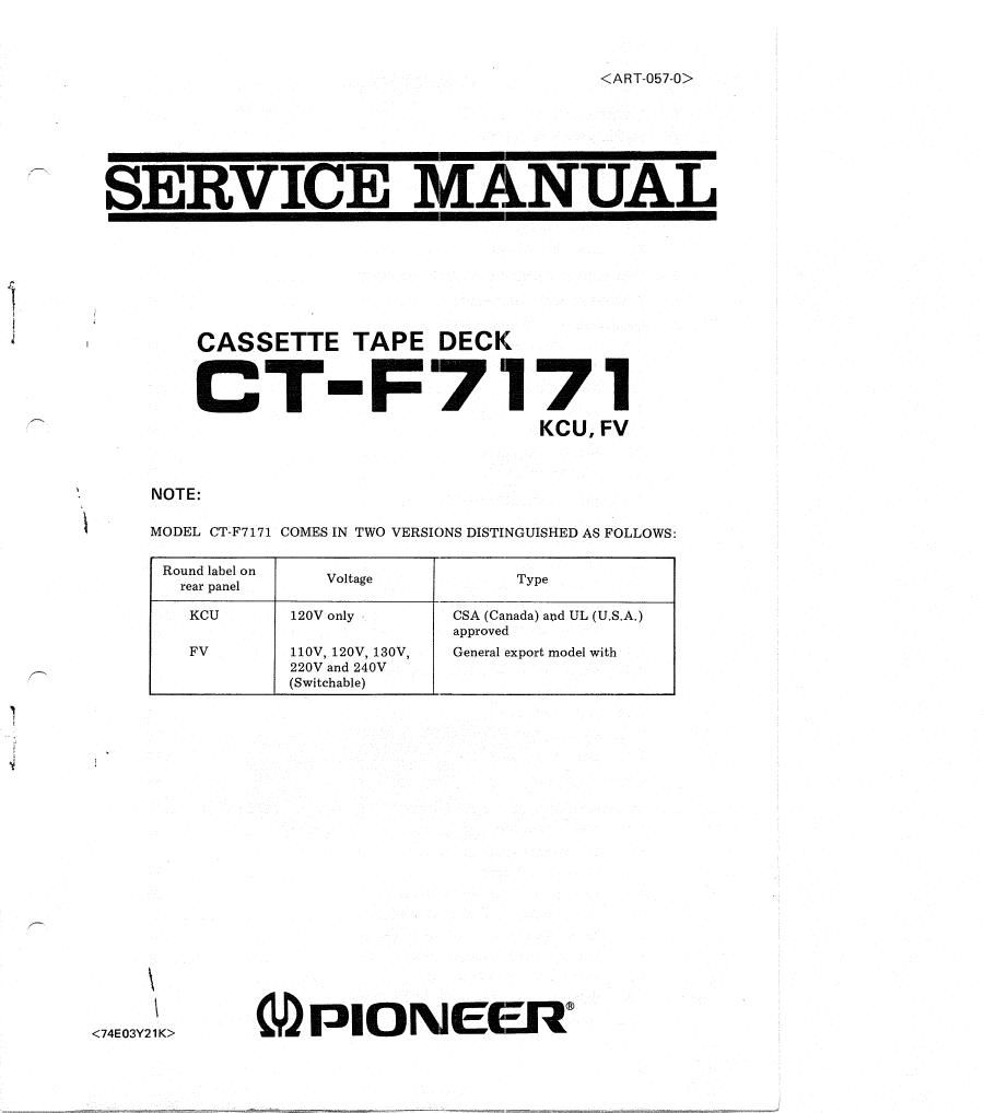
Pioneer ctf 7171 service manual
This is the 59 pages manual for pioneer ctf 7171 service manual.
Read or download the pdf for free. If you want to contribute, please upload pdfs to audioservicemanuals.wetransfer.com.
Extracted text from pioneer ctf 7171 service manual (Ocr-read)
Page 2
CONTENTS
SPECIFICATIONS ........................................ 4
PARTS IDENTIFICATION .................................. 6
CIRCUIT DESCRIPTION
3.1 Recordingand Playback Circuit .......................... 8
3.2 Auto Stop Circuit .................................... 10
3.3 Power Supply ...................................... 10
3.4 Subsidiary Circuits ................................... 11
DISASSEMBLY AND P.C. BOARD LOCATION .................... 12
TROUBLESHOOTING CHART ............................... 16
MECHANICAL ADJUSTMENTS
6.1 Pinch Roller Pressure ................................. 19
6.2 Take-up Torque ..................................... 20
6.3 Muting Switch ...................................... 21
6.4 Solenoid .......................................... 21
6.5 Play Switch ........................................ 21
6.6 Rec Actuating Lever .................................. 22
6.7 Tape Speed ........................................ 22
ELECTRICAL ADJUSTMENTS
7.1 Head Azimuth ...................................... 23
7.2 Playback Equalizer ................................... 23
7.3 Playback Level ......... , ............................. 23
7.4 Level Meter Calibration ................................ 23
7.5 Recording Current (Level) .............................. 23
7.6 Recording Bias ...................................... 23
7.7 Bias Trap ......................................... 24
7.8 Recording/Playback Frequency Response .................... 25
7.9 Recording Level ..................................... 25
7.10 g Peak Level Indicator . . . ............................. 26
7.11 Checking Operation of Limter ........................... 26
7.12 Dolby Processor ..................................... 26
LEVEL DIAGRAMS ....................................... 27
SCHEMATIC DIAGRAMS, P.C. BOARD PATTERNS AND PARTS LIST
9.1 Electro Parts List .................................... 28
9.2 Schematic Diagram ................................... 29
9.3 Connection Diagram .................................. 31
9.4 Lamp Board Assembly (RWX-052-0) ....................... 33
9.5 Indicator Board Assembly (RWX-053-0) ..................... 33
9.6 Terminal Board Assembly (RWX-054-0) ..................... 33
9.7 Sensing Circuit Assembly (RWR-OZS-A) ..................... 34
9.8 Switch Assembly (RWS-OZZ-A) ........................... 36
9.9 Dolby Processor Assembly (RWX-051-B) .................... 38
9.10 Limiter Circuit Assembly (RWX-OSO-AI ..................... 44