Pioneer ctf 7171 brochure
This is the 4 pages manual for pioneer ctf 7171 brochure.
Read or download the pdf for free. If you want to contribute, please upload pdfs to audioservicemanuals.wetransfer.com.
Extracted text from pioneer ctf 7171 brochure (Ocr-read)
Page 1
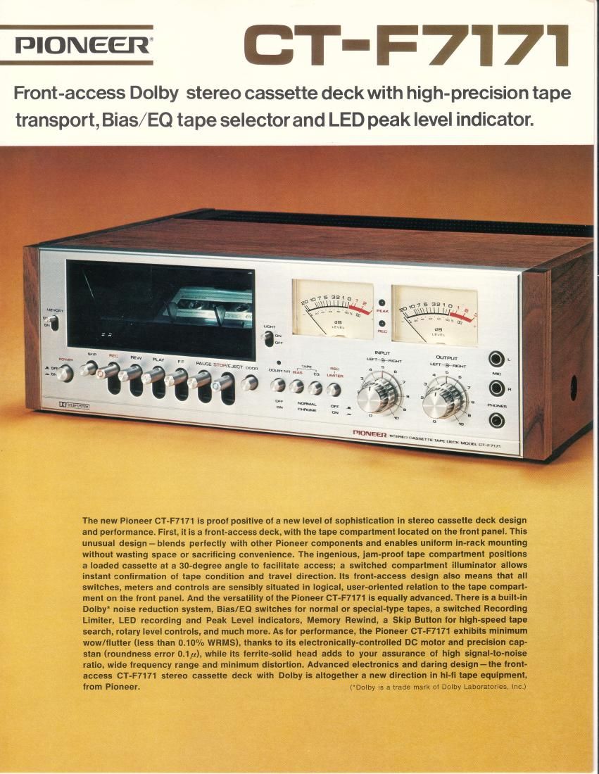
crrF:rl7l FRONT-CONTROL, F RONT-LOADING g9Q FRONT-ACCESS DESIGN All necessary deck operations including tape loading and unloading, are per- formed on the front panel. This daring design-a new direction in cassette deck thinking-enables you to mount the CT-F7171 in a component rack or on shelves along with your receiver, tuner, amplifier or other components. There's no need to waste space by providing vertical (top) ac- cess to the tape compartment or controls. The ingenious, jam- proof tape compartment itself is slanted at an angle of 30" to facilitate confirmation of taoe condition, aided by a switchgd compartment i I lum inator. ELECTRONICALLY-CONTROLLED DC MOTCIH Stability of tape travel and reliability of transport mechanisms are the decisive factors in high fidelity cassette deck performance. Pioneer therefore has applied the finest tape transport techniques available in the CT-F7171, a double-sure combination of a high- precision capstan shaft (roundness error 0.1p) and a dependable DC drive motor electronically controlled with a kind of servo-mechanism using solid- state devices to maintain precise drive voltage and stable rotation unaffected by power supply fluctuations. As a result, the wow/flutter characteristics of the Cf-F7171 have been reduced to a ratio of less than 0.10% (WRMS). RECORI}ING PEAK LEVEL INDICATOH Pioneer has developed a unique, simple-to-use Peak Level Indicator which detects the peak level of an incoming signal within a few milliseconds. The ?9983 seee -"4'* .:$rsir" w o000e $: LED (Light-Emitting DioOe) indicatorwill never flicker or burn out. lt reacts more quickly and with more sensitivity than any level or VU meter to the exact level of transient peak signal reaching the recording head. lt lights to warn you when the peak level of input is *4dB from refer- ence level, particularly handy when making Dolbyized re- cordings with low-distortion and wide dynamic range. SEPARATE BIAS AND EQ TAPE SELECTION The CT-F7171 performs perfectly with any cassette tape you wish to use- standard, low-noise/high-output or the types which are coated with special chrome and/or ferrite compounds. There are two front-panel switches, each with two positions (normal/chrome);the BIAS switch provides optimum bias current for low-distortion, while the EQ switch controls the "70ps" playback equalizer in the CT-F7171 (tor use with chrome dioxide tapes) to provide an improvement in the signal-to-noise ratio by approximately 4.5d8 (over SKHz) when measured against the normal "120ps" type. .*6 ggn @ .{+}/ k T--/\ %2+{")flI / - oAPSTAN \' i / lro_ ^_ nev\ ffil u J*.*@ s CIOLETY NF| TAPE F|EC t-----------IlEIIAS EA LIMITEFI RECORDING PEAK INDICATOR @ rrror r-isnt -,pa t'nn, -,p; r-ign, -Peak Indicator t4 1 Sine Wave (1,000H2) Signal Wave (Piano, etc.) High Frequency Signal Wave (Cymbal, Violin, etc.) --_ l - , ---l Level Meter l.--- l,--r | a Average level / is indicated. /,2 ,/ peak Level ELECTRONICALLY.CONTROLLED DC MOTOR CIRCUIT (CT-F7171) Power Switch of TaDe Deck --/"-----, Jg*-1_3 AC Power supply Power Translormer Power Source tor Recording, Playback Amplifiers At the STOP" operation mode this switch stops the motor rotation. (DC motor has strong starting torque.) Bridged AC+DC rectilier circuit Electronic control circuit that keeps constant current, voltage to the motor tor suppressing wow and flutter. Electronically-ControlledDC Molor (No Rotation Change between 50Hz and 60Hz Areas) ffis@s C'FFON NgFIlvIALcHFtotvtE C'FFON o.s E -l.-.
Page 2
BUILT-IN DOLBY NOISE REDUCTION Noise-free recording and playback performance are assured by the Type B Dolby circuitry in the CT-F7171 By boosting certain portions of the high- frequency spectrum during recording, and deemphasizing them during play- back, "tape hiss" is almost completely eliminated while those high{requency sounds you should hear are allowed to come through clean and clear. A separate Dolby indicator and a simple push-button Dolby switch provide all the control you need. RECORDING LEVEL LIMITER CIRCUIT Another simple-to-use front-panel switch handles the built-in recording level limiter circuit in the CT-F7171. Dis- tortion caused by over-level signals during recording is avoided by first setting the input level to optimum (using the large level meters and the Peak Level Indicator), then switching on the automatic limiter. This is the same kind of circuit used in studio-type equipment, not the ALC (automatic level control) de- sign found in portable type record- ers, and is therefore suitable for high fidelity use. the three-digit tape counter to "000" at the point on the tape from which you want to record (or play). When the tape has been recorded (or played) as far as you want it to go, flick the rewind switch and the tape will return to the "'999" position - in other words, to the place where you started. The handy Skip Button also is easy to use: I with the deck in the playback mode, a I touch of the Skip Button will allow you I to hear (monitor) the recorded sound I at twice-normal speed, helping Vou to I quickly locate any portion of the taOe I you desire. I MEMOFIY res HIGH-PERFORMANCE FFRRITE.SOLID HEAD Extended recording and playback life, greatly improved fidelity and other advantages are assured by the ferrite-solid REC/PLAY head used in the CT-F7171. The surface of this extra-hard, precision-gap unit is mirror-finished so that a smooth, constant head-to-tape contact is maintained, even with stiff chro- mium dioxide tapes. The head materialand design repel dust and have very small magnetic loss in the critical high-frequency region. MEMORY REWIND AND SKIP BUTTON The CT-F7171 is equipped with two additional convenience features. One is the Memory Rewind function: with the front-panel Memory switch "ON", set WIDE.DYNAMIC-RANGE RECORDING AMPLIFIER To assure that your recordings are able to reproduce the widest possible range of audio signals, Pioneer has included a recording amplifier of wide dynamic range. Maximum allowable MIC input is 9V with sensitivity of 0.2mV. Maximum allowable LINE input is also 9V against a sensitivity of 60mV. OTI-IER VERSATILE FEATURES (1)Standard-size professional micro- phone jacks (not the miniature pin-jack types) and stereo headphone jack on front panel. (2) Recording Peak Level Indicators. (LED)(3) Large, reliable level meters. (4) Rotary, friction-coupled input and output level controls for left and right channels with reference index markers. (5) Two pairs of input/output terminals, DIN standard jack and unswitched AC outlet (300W max.). (6) Distinctive front-access design, natural deluxe wood cabinet and metallic front. Alldimensions matched for installation with other Pioneer high-fidelity components (amplifiers and tuners). CrJTFUTffi-€Fniur t atl" ' *], LIMITER EFFECT Musical Input Signal Output Signal r@ Signal wave is clipping (Flat-Topping) OverLevel Portion r\FtlT|.F-€tsffi E (DPIoNEEFI'