Pioneer ctf 600 owners manual

This is the 14 pages manual for pioneer ctf 600 owners manual.
Read or download the pdf for free. If you want to contribute, please upload pdfs to audioservicemanuals.wetransfer.com.

Page: 1 / 14
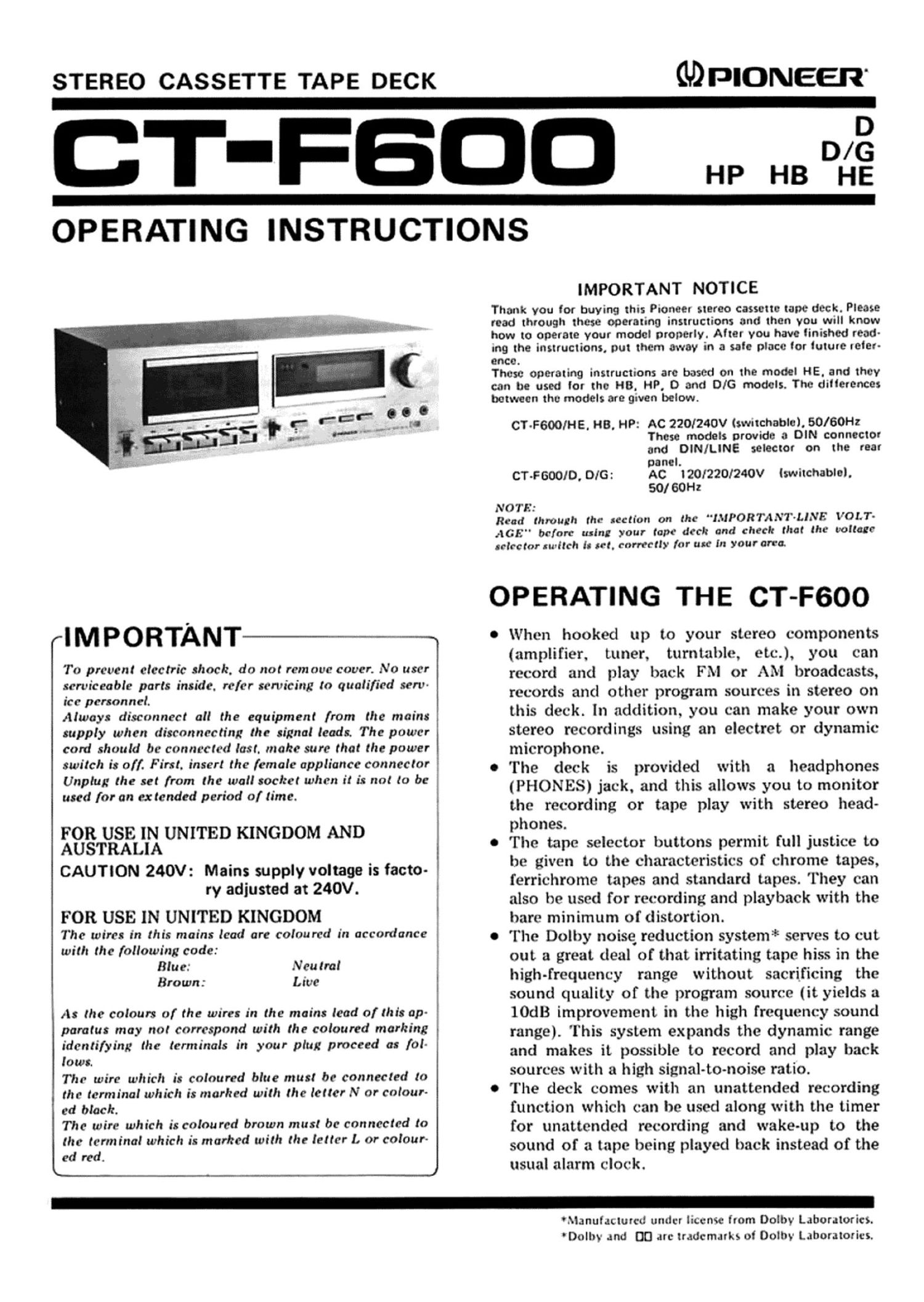
pioneer ctf 600 owners manual

Extracted text from pioneer ctf 600 owners manual (Ocr-read)


Page 1

STEREO CASSETTE TAPE DECK

GDPIONEER'

T-FBDD Hp 3°43

OPERATING INSTRUCTIONS

rlMPORTANT 1

To prevent electric shock, do not rem oue cover. No user
serviceable parts inside. refer servicing to qualified serv-
ice personnel.

Always disconnect all the equipment from the mains
supply when disconnecting the signal leads. The power
card should be connected last. make sure that the power
switch is off. First. insert the female appliance connector
Unplug the set from the wall sachet when it is not to be
used for an ex tended period of time.

FOR USE IN UNITED KINGDOM AND
AUSTRALIA

CAUTION 240V: Mains supply voltage is facto-
ry adjusted at 240V.

FOR USE IN UNITED KINGDOM

The wires in this mains lead are coloured in accordance
with the following code:

Btu e: N'eu tral

Brown: Live

As the colours of the wires in the mains lead of this ap-
paratus may not correspond with the coloured marking
identifying the terminals irt your plug proceed as fol-
laws.

The wire which is coloured blue must be connected to
the terminal which is ntarhed with the letter N or colour-
ed black.

The wire which is coloured brown must be connected to
the terminal which is marked with the letter L or colour-
ed red.

Q J

IMPORTANT NOTICE

Thank you for buying this Pioneer stereo cassette tape deck. Please
read through these operating insuuctions and then you will know
how to operate your model properly. Alter you have finished read-
ing the instructions. put them away in a sale place tor luture retar-

ence.
These operating instructions are based on the model HE. and they
can be used lor the H8, HP, 0 and DIG models. The ditlerences
between the models are given below.

CT-FGOOIHE. H8, HP: AC 220(240V (switchable). 50/60Hz
These models provide 3 DIN connector
and DIN/LINE seleCtor on the rear

paneL
CT-FGOOID, DIG: AC l201220/240V (switchable).
50/60Hz

NOTE:
Read through the section on the "l.%lPORTAa\"I'-LINE VOLT-

AGE" before uslna your tape deck and check that the voltage
"(cum pitch is set, correctly for use in youran-a

OPERATING THE CT-FGOO

0 When hooked up to your stereo components
(amplifier. tuner, turntable, etc.), you can
record and play back FM or AM broadcasts,
records and other program sources in stereo on
this deck. In addition, you can make your own
stereo recordings using an electer or dynamic
microphone.

0 The deck is provided with a headphones
(PHONES) jack. and this allows you to monitor
the recording or tape play with stereo head-
phones.

0 The tape selector buttons permit full justice to
be given to the characteristics of chrome tapes,
ferrichrome tapes and standard tapes. They can
also he used for recording and playback with the
bare minimum of distortion.

0 The Dolby noise reduction systemc serves to cut
out a great deal of that irritating tape. hiss in the
high-frequency range without sacrificing the
sound quality of the program source (it yields a
IOdB improvement in the high frequency sound
range). This system expands the dynamic range
and makes it possmle to record and play back
sources with a high signal-to-noise ratio.

0 The deck comes with an unattended recording
function which can he used along with the timer
for unattended recording and wake-up to the
sound of a tape being played back instead of the
usual alarm clock.

'hlanulacturcd under license from Dolby Laboratories.
'Dolhy and DC] are trademarks of Dolby Laboratories.

Page 2

FRONT PANEL FACILITIES

POWER SWITCH

Power is supplied to the deck which this switch is set to ON, and
the level meter lights up.

ASSETTE HOLDER

The cassette tape is loaded into this holder. When the STOP]
EJECT (I i lever is depressed, the holder will jump forward. To
close it, push the top part of the holder back Into position until It
is locked.

RECORD INDICATOR

This light comes on when the play (Di and REC levers are de-
pressed together to indicate that the cassette deck is now set to the
recording mode.

TIMER START SWITCH

Set this switch to ON when you are making use of the unattended
recording or wake-up playback function together with the timer.
For details, read the section on page 8 entitled "Recording and
playback using the timer." When the PAUSE lever is depressed,
this switch is released to the OFF 9 - sition.

INPUT LEVEL CONTROLS

Use these controls to adjust the Input signal from the MIC lacks
and the rear panel lNPUT lacks. Turning them to the right in-
creases the signal level. They are coupled to the left and right
channels when rotated, but you can also use them to adjust the
right channel and left channel independently by rotating the
appropriate control and holding the other in position.

Lelt channel Rinht channel

0 UNTER RESET BUTTON/TAPE COUNTER
Depress this button to reset the tape counter display to 000."
Tape counter indicates the position of the tape run.

LEVEL METERS

These indicate the input level during recording and the output
level during playback.

DOLBY NR SWITCH
Push this button to GM for recording with the builtoin Dolby noise
reduction system and for the playback oi tapes which have been
recorded using the Dolby NR system.

DOLBY NR INDICATOR

This light comes on when the DOLBY NR switch is set to ON to
indicate that the cassette deck is now set up for recording using
the Dolby NR system or playback using the Dolby NR system.

TAPE SELECTOR SWITCHES

Depress the switch which corresponds to the type of tape you are
using (refer to Using the tape selector switches on page 7).

STD: For ordinary tapes. and LH tapes.

Fe-Cr: For ierrichrome tapes

00,: For chrome tapes

MIC JACKS
These are the input jacks for microphone recording. Plug the left
channel microphone Into L and the right channel microphone
into R.

NOTE:
Disconnect your microphones from the who! when you on

not train: them. orhemiu you will not be able to record to
LINK and DIN input reminds.

HEADPHONE JACK

This is the output lack for stereo headphones. Plus your head-
phones into this lack when you want to monitor the quality of a
recording or when you want to listen to a tape privately.

NOTE:
Do not connect a microphone to this Joe-Ir or the microphone
may be demand.