Pioneer ctf 4242 schematic
This is the 3 pages manual for pioneer ctf 4242 schematic.
Read or download the pdf for free. If you want to contribute, please upload pdfs to audioservicemanuals.wetransfer.com.
Extracted text from pioneer ctf 4242 schematic (Ocr-read)
Page 1
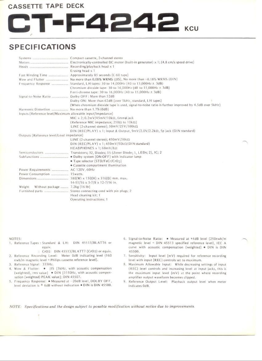
# CASSETTE TAPE DECK
CT'F4242
SPECIFICATIONS
Systems . CttmdeI cassette, 2-channel stereo
Moron .. . . Electronicallycontrolled DC motor (builbin generator) x I;(4.8 cm/s speed drive)
Heads ........................................ Recording/playback head x I
Erasing head it I
lel Winding lime Approximately 35 seconds ((450 tape)
Woss and Flutter .. No more than 0.08% WRMS (HS), No more than vt).l8% WRMS (l)IN)
liequt-ntv Response standarml H tapes: 30 to I4,l)00H/ (40 to I I,000HI t 3dBl
Chromium dioxide tape: 30 to 16,000Il/ (40 to 15,000H/ x 3dB)
I'etriwhimne tape: IO to 3,000HI (40 to l5,00()HI t 'IdB)
Dolby OFF: More than 52413
Dolby ON: More than 62dB (over Skill, standard, I H tapes)
(When chromium dioxide tape is used. signal-to-noise ratio is lurther improved by 4.5dB ovcr Skill)
Harmonic Distortion .......... No more than 1.7%(0dB)
Inputs (Relerente level/Maximum allowable input/lmpedante)
MIC x 2; 0.2mV/4imV/I0ktl, (immil lack
(Reference MIC impedance; 250 to mini)
LINE (2-channel stereo); SOmV/ZSV/IOOHZ
DIN (REC/PLAY) x I: Input & Output. 9mV/2.0v/2.2kn, Sp tack (DIN standard)
Outputs (Reference level/Load impedance)
LINE (2-ctiannul stereo); 450mV/50Ml
DIN (REC/PLAY) x I;450mV/50ktz(DIN standard)
HEADPHONES x I; 60ntV/IISZ
Transistors; 32, Diodes; IS (chcr Diode; l, LEDs; 2), IC; 2
n Dolby system (ON-OFF) with indicator lamp
a rape selector (STD/FeCr/(IrOz)
o Cassette compartment IiiUmIndllon
AC l20V. 60H!
|5watts.
580(W) x l50(H) x SlbiD) mm. mas.
Malfi/It) it 57/8 x 117/16 in.
7.2mm; lb)
Stereo Lonneuing cord wuh pin plugs; 2
Head cleaning kit; I
Operating iristructionsfl
Signal-tierse Ratio.
\t'mlttlndtulnrs
Subtunctions ..
Power Requirements .
Power Consumption
Dimensions ........
Weight Without package ,
I iirnished parts .
NOTES 6. Signal-to-Noise Ratio: I Measured at +4113 level (ZSOnwb/m
I. RelerenceTapes1§tandard 5i LH: DIN 45SI3/BLAITb or magnetic level : DIN 45513 specified relerence level). IEC A
equiv. curve with acoustic compensation (weighted) 0 DIN is DIN
CrOz: DIN 455I3/BLA1T7 (Cr02)ur equiv. 45500.
2. Relcrence Recording Level: Meter OdB indicating level (I60 7 sensitivity: Input level (mV) required Ior reference recording
nwb/m magnetic level = Philips cassette reierente level). level with input (REC) controls set to maximum.
1. R?iC'C"L€ Signal: 333). ll Maximum Allowable Input: While decreasing settings 0! input
4. Wuw & Hutlcr: o IIS (3km, wrth acoustin sompcnsation (RLC) level controls and increasing level at input lacks, ihis is
(weighted), this value] ' DIN NONI, Wilh dCtlUSIlL cumnerr the maximum input level (mV) at the point where recording
sation (weighted) PEAK value|; DIN 45507. amplifier output waveform becomes clipped.
5. Fteaurmv Response: I Measured all *2003 IBVEIVDOLBY CHI 9. Reference Output Level: Playback output level when meter
level deviation is I de without indication 0 DIN is DIN 45500. Indicates OdB.
NOTE Spert/iwlions and the design subject In possible modification without notice due [0 improvements.