Pioneer ct 320 service manual

This is the 4 pages manual for pioneer ct 320 service manual.
Read or download the pdf for free. If you want to contribute, please upload pdfs to audioservicemanuals.wetransfer.com.

Page: 1 / 4
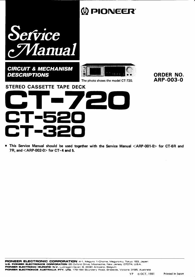
pioneer ct 320 service manual

Extracted text from pioneer ct 320 service manual (Ocr-read)


Page 1

(U) PIONEER

Sefiice
(71451111131

CIRCUIT & MECHANISM

DESCRIPTIONS

. V _ h ' ,, - , ORDER NO.
The photo shows the model CT-720. ARP-003-0
STEREO CASSETTE TAPE DECK

T-7EU
CT-EED
CT-aao

I This Service Manual should be used together with the Service Manual for CT-GR and
7R, and for CT-4 and 5.

PIONEER ELECTRONIC CDHFDRATION 4-1, Msgurn l-Chcma, Maguro-ku. Tokyo 153 Japan
LLB. DION- 35:11:09:ch monA'nON BE Oxford Drwa Moonauhie, New Jersey 07074. USA.
Emilia ELECTRON": (WE) N.V. Luuchagen-Haven a 2030 Antwan], Eslglum

Bmn mica AuamuA u'rv. Lm. 178-184 Boundary Road. Eraesme. Vccoma 3155. Auscmha

YP ©OCT. 1981 Plinled in apan

Page 2

CT-720/520/320

1. CT- 720

Block Diagram

yo REC/re mo
MHLYER DOLBV NR SVSTEM REC MUTE REC E0 AMP

@ m . [W m.


an m-
u .n-l

um

um sum

W m
i im

NEVER IMP nmvm

k .a i.
i W, m m.
0 IIIYALI
.l. .4419. .

i

3
I m.
are: 3% n

sic: iflEnL
_ "m comam Clacun' 5mm
7% 5 5.0. mm W mm
| c")! 7 5 SIOZ [lull vulva" DEYECNI
am Voicing muse , 191w ms ' run/m uneven
imam 2 m. \ i sin: (Lt-mu:
0 @ ow: ULNVOKI SMI VIN: SELICVOI

mm as: mmmn ,. 2° ,2 no: ms uucm
( ) . no: new a
" sine . mm: mm

(Mann-w

POWER SUPPLY


m. ~ mrvr mm
cam-colours , (:9 mm m,
H i w A no: i m
W, W 4 -I Hi i i _ a 04 v m:
A: 04 no: ' c
-mm \ \ \ \ .. m :3: :2 m
$001360! luau isms ssav "IL v! I E III
was «as m- (D m mater-an
-W2°vv u 4' sum : mm-
m. .....
W i. m,
w
mm. mm.
.m. om...
mm suncu.
Icm uremia m mm
I rsrourucv 533m 5
mm

Refer to the block diagram for circuit details. The Dolby NR processor output (pin 8 of
HA11226) is applied to the REC/PB head via the
1-1 S'GNAL PATHS REC muting circuit (Q306/Q307), the recording
Playback Mode amplifier (Q308) and a bias trap.
The signal from the REC/PB head is passed via . . _
the equalizer amplifier (Q301/Q302), a bilateral ° F "16°th Descnptmsi f t0 the

. - - Service Manual (CIRCUIT & MECHANISM
swrtch (10303), a flat amplifier (Q304) and MPX
filter to the Dolby NR processor (pin 2 of DESCRIPTIONS) for CT-6R
HA11226). The Dolby NR processor output (pin 8 and 7R"

of HA11226) is passed to the LINE OUTPUT via
another bilateral switch (10304) and the line
muting circuit (Q309/Q310).
Recording Mode

The LINE INPUT signal or MIC signal (mic
amplifier output) is passed to the Dolby NR
processor (pin 2 of HA11226) via the INPUT
level control (VR801), a bilateral switch (IC303),
a flat amplifier (Q304) and MPX filter.