Pioneer a 51 service manual

This is the 24 pages manual for pioneer a 51 service manual.
Read or download the pdf for free. If you want to contribute, please upload pdfs to audioservicemanuals.wetransfer.com.

Page: 1 / 24
pioneer a 51 service manual

Extracted text from pioneer a 51 service manual (Ocr-read)


Page 1

service"
Wanna]

I

(V) PIONEER

The Art of Entertainment

m _ . ORDER NO.
Q L==J ARP225 1
STEREO AMPLIFIER
A - 7 7 7
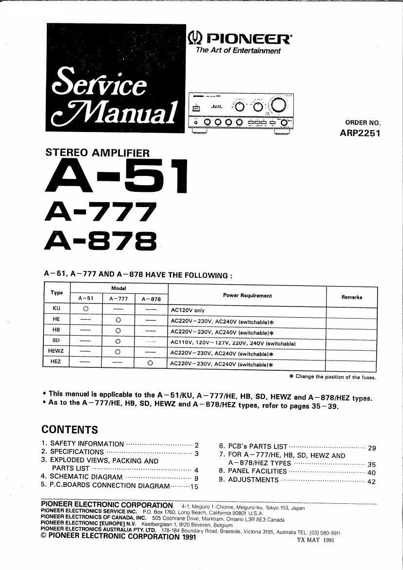
A - 51 . A-777 AND A-878 HAVE THE FOLLOWING :
Model
Type Power Hoqulramam Remarka
A-51 A~777 A-876
KU O - AC120V anly
HE - O - A0220V~230V, AC240V (switchablsl*
HB --- O - ACZZOV-ZSOV, ACZ4OV (switchable)*
SD - O - AC110V, 120V-127V. 220V. 240V (switchable)
HEWZ -- O - ACZZOV-ZSOV, ACZ40V Iswichablow
HEZ - -- O AC220V-230V, ACZ40V (switchablaII

* Change the position of the lusss.

0 This manual Is applicable to the A-SI/KU, A-777/HE, HB, SD, HEWZ and A-878/HEZ types.
- As to the A-777/HE, HB, SD, HEWZ and A-878/HEZ types, refer to pages 35-39.


CONTENTS

1. SAFETY INFORMATION ---------------------------- 2 6. PCBs PARTS LIST ------------------------------------ 29

2. SPECIFICATIONS --------------------------------------- 3 7. FOR A-777/HE, HB, SD, HEWZ AND

a. EXPLODED VIEWS, PACKING AND A-B78/HEZ TYPES ------------------------------- 35
PARTS LIST --------------------------------------------- 4 a. PANEL FACILITIES I ~ 40

4. SCHEMATIC DIAGRAM ------------------ 9 9. ADJUSTMENTS --------------------------- 42

5. P.C.BOARDS CONNECTION DIAGRAM --------- 15

PIONEER ELECTRONIC CORPORATION 4-1 Meguro 1~Chome, MeguroAku. Tokyo 153. Japan
PIONEER ELECTRONICS SERVICE INC. R0. Box 1760, Long Beach, CalIfornIa 90801 U,S.A,

PIONEER ELECTRONICS OF CANADA, INC.

505 Cochrane Dnve, Markham. Onlano L3H 8E3 Canada

PIONEER ELECTRONIC [EUROPE] N.V. Keelberglaan 1, 9120 Beveren, BBIQIUITI
PIONEER ELECTRONICS AUSTRALIA PTY, LTD.

© PIONEER ELECTRONIC CORPOR

178484 Boundary Road Braeslde, Vlctona 3195, AustralIa TEL: [031580-9911
ATION 1991 YX MAY 1991

Page 2

This service manual is intended for qualified service technicians; it is not
meant for the casual do-it-yourselfer. Qualified technicians have the neces-
sary test equipment and tools, and have been trained to properly and safely
repair complex products such as those covered by this manual.

Improperly performed repairs can adversely affect the safety and reliability
of the product and may void the warranty. If you are not qualified to
perform the repair of this product properly and safely, you should not risk
trying to do so and refer the repair to a qualified service technician.

WARNING

Lead in solder used in this product is listed by the California Health and Welfare agency as
a known reproductive toxicant which may cause birth defects or other reproductive harm
(California Health at Safety Code, Section 25249.5).

When servicing or handling c

it boards and other components which contain lead in

solder, avoid unprotected skin contact with the solder. Also, when soldering do not inhale

any smoke or fumes produced.

1. SAFETY INFORMATION

'(FOR USA MODEL ONLY)
1.5AFETY PRECAUTIONS

The following check should be performed for the
continued protection of the customer and service
technician.
LEAKAGE CURRENT CHECK

Measure leakage current to a known earth ground
lwater pipe, conduit, eth by connecting a leakage
current tester such as Simpson Model 229-2 or
equivalent between the earth ground and all exposed
metal parts of the appliance (input/output terminals,
screwheads, metal overlays, control shaft, etc.l. Plug
the AC line cord of the appliance directly into a 120V
AC 60H: outlet and turn the AC power switch on. Any
current measured must not exceed 0.5mA.


Reading should
we not be above

Device current 05?
under tester
lest '
Test all
exposed metal
surfaces
2-wtre com

® Also teal wllh

plug image tmn

(Using AC adaptei ground
plug as required)

L AC Leakage Test

ANV MEASUREMENTS NOT WITHIN THE LIMITS
OUTLINED ABOVE ARE INDICATIVE OF A P0-
TENTIAL SHOCK HAZARD AND MUST RE COR»
RECTED BEFORE RETURNING THE APPLIANCE TO
THE CUSTOMER

2.PHODUCT SAFETY NOTICE

Many electrical and mechanical parts in the appii~
ance have special safety related characteristics. These
are often not evident from visual inspection nor the
protection afforded by them necessarily can be ob
tained by using replacement components rated for vol-
tage, wattage, etc. Replacement parts which have
these special safety characteristics are identified in
this Service Manual.

Electrical components having such features are

identified by marking with a A on the schematics and
on the parts list in this Service Manual.
The use of a substitute replacement component which
dose not have the same safety characteristics as the
PIONEER recommended replacement one. shown in
the parts list in this Service Manual. may create shock,
fire, or other hazards.

Product Safety is continuously under review and
new instructions are issued from time to time. For
the latest information, always consult the current
PIONEER Service Manual. A subscription to, or ad-
ditional copies of, PIONEER Service Manual may be
obtained at a nominal charge from PIONEER.

2. SPECIFICATIONS
lA-Ei/A-777l

Continuous Average Power Output ' 100
Watts' per channe m at 8 ohms from
20 Hertz to 20,000 w h no more than
0.007% total harmonic distortion.

Continuous Average Power Output is 135
Watts per channel, min., at 4 ohms from
20 Hertz to 20,000 Hertz. with no more than
0.009% total harmonic distortion.

- ~ - Measured pulmm to the Federal and: Commlssione Trade
Regulation rules on Power culpul Claims lol Amphflevs.

Conlinuous power output (both channels driven at 20 Hz to 20 km
u.l< model
me. 0.007 tr... e u
T H. once so. 4 ti
Multi-voltagc modeis
T.H.D. 0.007 to. all. oow + 100 w-
TH possum. 40w+l4ow'
cw Continuous powor output [both marinas driven at l kal
mu. 1.0 so. a n . 100 w + loo w
m.oio%.m .I50W4150W
Power bandwidth
0.05 as. a ll ...........
Damping factor

.95W 4 95W
.lan e lew

5 H1 , 80 kHz

ll kHt/ZO Hz to 20 kHzl, B n 150/70
D namic el output [on EIA dynamic test signal
I "/2 01. .. 220 Wiaso w
Total harmonic distortion
U K. model
20 Ht to 20 kH1,95 W. a S) 0.007 %.
20 Hz to 20 kHl, 0 w. 4 ll. 0.009 36

Mullivollsoe moaei .
20 H1 in 20 kHz, wow. 5 c. 0.007 as

20 Hz to :0 kHz,140 w, 4 (I. 0.009 as:
lnierrrlodulallorl distortion lat rated wlpull. 0.007 "It
Input sensitivityfimvcdance

PHDNO (MM). 25 mV/50 kl!
PHONO lMCl, . 0.2 lily/I00 it

150 mV/50 kll

CD, TUNER, LlNE, TAPE
PHOND overload level

1 kH1,TH D. 0.008 Io (MM/MC) ......... 200 mvne mv
Oulpul levemmpednnce

TAPE REC. ADAPTOR OUTPUT . ,, .. . ,. . 150 nil/12.1 kll
F response

mum z 0.2 as

PHONO MM). 20 Ht la 20 m:
PHONO (Mcy, 20 H! to 20 kHz
CD. TUNER. LINE. TAPE, 1 Hz to 150 kHz
Tone control iwlumc control set nl 7A0 dB p


1 0.3 on
:lae-

: E as (100 Hzl

BASS. . . .
THEBLE . z 8 do no kHzl
MUTING. . » ac

Loudness conloul (volume control set at - 40 dB position)
. +5 as use fill/+3 dB no kHz)

. . i7 H1112 oelocll
, networki
PHONO MM, 5 mv input/MC, o 5 mV input). 54 dBlIE oa-
CD. TUNER, LINE, TAPE . .. 110 dB

SignQHOvNolse ratio will. conllnuous power/50 nlWl
PHONO IMMI
CD, TUNER. Ll

74 dB/GB dB'
. 92 ids/70 dB'


A 5 1
Power Supply/Miscellaneous
remants
PEWSEZ ..... Ac lzo v. so Hz
uK. mode . . or. 240 you». 50/60 H1

.Ac lie/120 - 117/220l24o V

Mullivvolha e models
9 lswnchacle). 50/60 Hz

ster Donaumlmon
us model .
UK. mooe
Multiwltage models
AC outlets ids. and
Swllched ix 2i.
Unswltchad (x ll
Dimensions ......

woitaga models)

420 (Wl x 435 (D) x 1621lenlrl
IB~91lSlWI x l7-l/81Dlx sale ml in
Weight (without package) . is kg (4| lb: 14 oz)

Accessories
Operating inslruclions .
Cushion spacer sat...


more: .. .
sml/murions and «Sign subject lo possible Ml'lClIIO" willloul
"price due to mmmms

' When the DIRECT button to ON.
" Measured by Audio Spectrum Analyzer,

Be sure to place the unit on a level surface so lhll it stands llrrrlly
on III S leet. II wobbly. Idiull by ill-clung the supplied cusnlon
spacers to one or more feet.

rulilism uv vipntu Electronic EOlWIlinn
Copyrlth c issl Planezi Elltllflrllc Eomoralmn
All will was