Pioneer a 509 r owners manual

This is the 12 pages manual for pioneer a 509 r owners manual.
Read or download the pdf for free. If you want to contribute, please upload pdfs to audioservicemanuals.wetransfer.com.

Page: 1 / 12
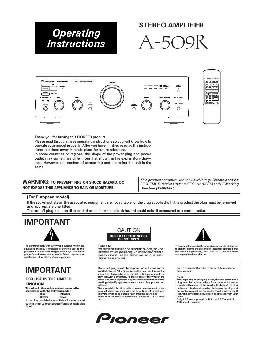
pioneer a 509 r owners manual

Extracted text from pioneer a 509 r owners manual (Ocr-read)


Page 1

2 OPERATIONS ............................................................................... 8 REMOTE CONTROL .................................................................... 9 TROUBLESHOOTING ................................................................ 11 SPECIFICATIONS ......................................................... back cover FEATURES ................................................................................... 2 INSTALLATION ............................................................................ 2 CONNECTIONS ........................................................................... 3 PANEL FACILITIES ...................................................................... 5 CONTENTS FEATURES ¦Advanced Direct Energy MOS Power Amp Pioneer incorporates highest quality amp circuitry featuring Advanced Direct Energy MOS FET devices which can achieve higher performance. Together with Pioneer's original Wide Range Linear Circuit technology they reduce power consumption while maintaining the power output of current models. In terms of performance, this technology contributes to flat damping factor characteristics across the audio spectrum. It also allows a wide range and especially ultra high frequencies to be reproduced more accurately and improves power linearity. ¦Stabilizer Transformer stabilizer, stabilizer frame (attached to chassis) and volume stabilizer (attached to volume knob) deliver powerful sound. LOCATION Install the unit in a well-ventilated location where it will not be exposed to high temperatures or humidity. Do not install the unit in a location which is exposed to direct rays of the sun, or near hot appliances or radiators. Excessive heat can adversely affect the cabinet and internal components. Instal- lation of the unit in a damp or dusty environment may also result in a malfunction or an accident. (Avoid installation near cookers etc., where the unit may be exposed to oily smoke, steam or heat.) Do not install the unit on a tottered stand, nor on an unstable or inclined surface. VENTILATION ¥ When installing this unit, make sure to leave space around the unit for ventilation to improve heat radiation (at least 60 cm at top, 10 cm at rear, and 30 cm at each side). If not enough space is provided between the unit and walls or other equipment, heat will build up inside, interfering with performance or causing malfunctions. ¥ Do not place on a thick carpet, bed, sofa or fabric having a thick pile. Do not cover with fabric or other covering. Anything that blocks ventilation will cause internal temperature to rise, which may lead to breakdown or fire hazard. INSTALLATION CONDENSATION When the unit is brought into a warm room from previously cold conditions or when the room temperature is suddenly increased, condensation may form inside and the unit may not be able to attain its full performance. In cases like this, allow the unit to stand for about an hour or raise the room temperature gradually. POWER-CORD CAUTION Handle the power cord by the plug. Do not pull out the plug by tugging the cord and never touch the power cord when your hands are wet as this could cause a short circuit or electric shock. Do not place the unit, a piece of furniture, etc., on the power cord, or pinch the cord. Never make a knot in the cord or tie it with other cords. The power cords should be routed such that they are not likely to be stepped on. A damaged power cord can cause fire or give you an electrical shock. Check the power cord once in a while. When you find it damaged, ask your nearest PIONEER authorized service center or your dealer for a replacement. NOTES:ÖIf you use an other power cord than provided, we cannot assume the liabilities in what may occur as a result of it. Ö(The provided power cord has a current capacity of 2.5 A.) ¦Designed for Low Power Consumption This model incorporates several features for energy efficiency to reduce power consumption. 1Direct Energy Circuit 2Local Off circuit: Tone Local Off, Phono Local OFF, Silent Microcomputer 3S-MOS: Instead of the digital transistors usually used in logic circuits, this unit employs S-MOS devices in some areas. These do not require base current, so they help re- duce power consumption. ¦Energy-Saving Design This unit is designed to use minimal electricity when power is switched OFF (during Standby). Regarding the value of the power consumption in standby mode, refer to ÒSPECIFICATIONSÓ on page 12 (back cover).

Page 2

3 SIGNAL GND PHONO TUNER LINE/ SURROUND BACK TAPE1/CD–R/MD TAPE2 MONITOR CD IN IN IN IN OUT IN OUT INREC PLAY REC PLAY L RL R R RL L B A SPEAKERS CONTROL OUT AC INLET FM-AM CD DVD RECPLAY L R L R AUDIO OUT RECPLAY L R L R L R OUTPUT L R OUTPUT LR LR LR LR LR LR LR LR LR LR LR LR INOUT LR LRLR LR LR á » » á á á » » AC OUTLET SWITCHED 100W MAX CONNECTIONS Before making or changing the connections, switch off the power switch and disconnect the power cord from the AC outlet. Cassette deck/MD recorder Adaptor component (graphic equalizer, etc.) Cassette deck/ CD recorder/ MD recorder CD playerDVD player, VCR, etc.See page 4. Speaker system B (Left) (Right) To an AC wall socket. TunerTurntable Illustration shows U.K. model See page 4. European model only Speaker system A (Left) (Right)