Pioneer a 103 service manual

This is the 20 pages manual for pioneer a 103 service manual.
Read or download the pdf for free. If you want to contribute, please upload pdfs to audioservicemanuals.wetransfer.com.

Page: 1 / 20
pioneer a 103 service manual

Extracted text from pioneer a 103 service manual (Ocr-read)


Page 1

(ID PIONEER

The Art of Entertainment

Service
Manual

STEREO AMPLIFIER

A-203
A-1 03

THIS MANUAL IS APPLICABLE TO THE FOLLOWING MODEL(S) AND TYPE(S).

ORDER NO.
ARP2 8 5 2

04010

(:3)ij ._ 33-5

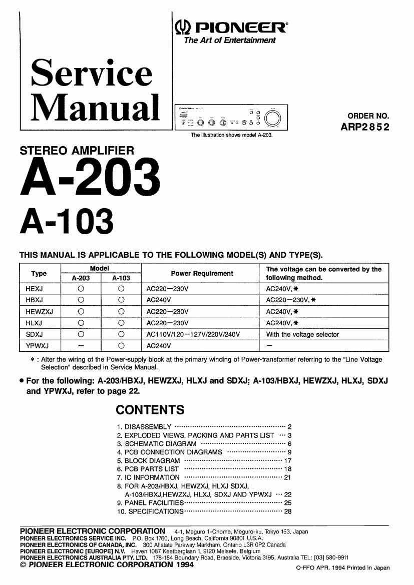
The illustration shows model A-203.

Type A203Model A403 Power Requirement Tgafirsgfieizgge convened by the
HEXJ O O A0220 -230V AC240V, 4t-
HBXJ O O A024ov A0220 -230v, *
HEWZXJ O O A0220 --230V ACZ40V, *
HLXJ O O A0220 -230V AC24OV, ll-
SDXJ O O AC110V/120-127V/220V/240V With the voltage selector
YPWXJ - O A0240V -

at : Alter the wiring of the Power-supply block at the primary winding of Power-transformer referring to the Line Voltage
Selection" described in Service Manual.

0 For the following: A-203/HBXJ, HEWZXJ, HLXJ and SDXJ; A-103/HBXJ, HEWZXJ, HLXJ, SDXJ
and YPWXJ, refer to page 22.

CONTENTS
1- DISASSEMBLY ................................................... 2
2. EXPLODED VIEWS. PACKING AND PARTS LIST 3
3. SCHEMATIC DIAGRAM 6
4. PCB CONNECTION DIAGRAMS " 9
5- BLOCK DIAGRAM ............................................. 17
6- PCB PARTS LIST ............................................. 18
7_ IC INFORMATION ............................................. 21
8. FOR A-203/HBXJ, HEWZXJ, HLXJ SDXJ,
A-103/HBXJ.HEWZXJ, HLXJ, SDXJ AND YPWXJ 22
9. PANEL FACILITIES ............................................. 25
10. SPECIFICATIONS ............................................. 28

PIONEER ELECTRONIC CORPORATION 4-1. Meguro 1-Chome. Meguro-ku. Tokyo 153. Japan

PIONEER ELECTRONICS SERVICE INC. PO. Box 1760. Long Beach, California 90801 USA.

PIONEER ELECTRONICS OF CANADA, INC. 800 Allstate Parkway Markham. Ontano L3R 0P2 Canada

PIONEER ELECTRONIC [EUROPE] N.V. Haven 1087 Keetberglaan 1. 9120 Melsele. Belglum

PIONEER ELECTRONICS AUSTRALIA PTY. LTD. 178-184 Boundary Road. Braeside. Victoria 3195. Austraha TEL: [03] 580-9911

© PIONEER ELECTRONIC CORPORATION 1994 om; 31994 Primed in Japan

Page 2

A-203, A-103 l

1. DISASSEMBLY

O CHECKING FOR POWER AMP ASSY
1. Remove the bonnet. ® g /® /®
2. Remove the VOLUME knob and unscrew nut the ® (Fig. l). E/

3. Unscrew the fastening screws (D of the front panel (2 upper
and 5 lower screws. ).

4. Unscrew the fastening screws ® (1 screw) and @ (2 screws)
of the RADIATOR.

5. Lift up the RADIATOR (in the direction of the arrow @)
approximately 5mm, and remove it from the chassis hook.

6. Remove the lower hooks of the front panel (2 places).
7. Slowly remove the front panel together with the RADIATOR.

When doing this, be careful so that the flat cable CD form CN
1 does not get caught.

8. When the VOLUME knob shaft © has been distanced from
the front panel. lower the fins of the RADIATOR as shown
in Fig. 2 and raise the shaft.

0 HOW TO REMOVE THE POWER AMP ASSY

1. Remove the fastening screw ® of the RADIATOR (1 screw)
and (Q (2 screws) and the center fastening screw @ (1
screw) of the POWER AMP ASSY (Fig. 1).

2. Lift up the RADIATOR (in the direction of the arrow @)
approximately 5mm, and remove it from the chassis hook.

3. Pull the RADIATOR backward and remove the POWER
AMP ASSY and RADIATOR together.

Note : The CONTROL ASSY of the front panel and the
POWER AMP ASSY are connected only with
connectors. and they can the refote be easily removed by
carrying out the above opemtions,

Fig.2