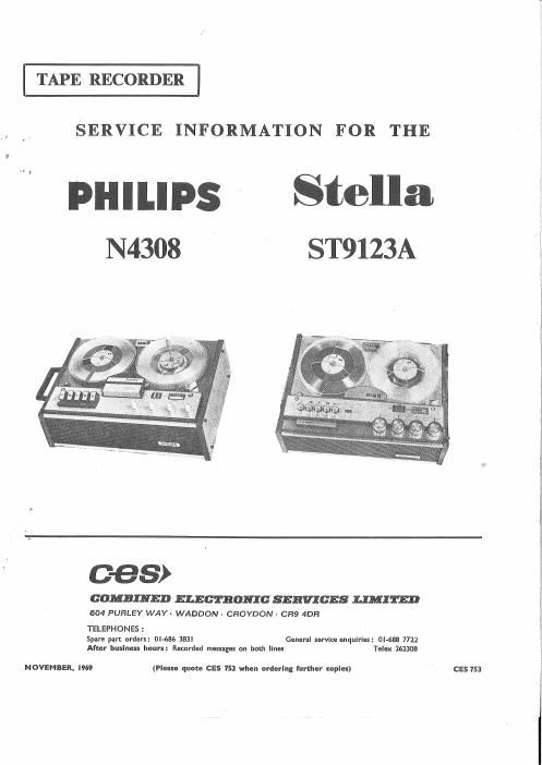
Philips n 4308 tape
This is the 19 pages manual for philips n 4308 tape.
Read or download the pdf for free. If you want to contribute, please upload pdfs to audioservicemanuals.wetransfer.com.
Extracted text from philips n 4308 tape (Ocr-read)
Page 1
TAPE RECORDER
SERVICE INFORMATION FOR THE
PHILIPS Stella
N4308 ' ST9123A
C-GS)
COMBINED ELECTRONIC SERVICES LIMITED
604 PURLEY WAY- WADDON- CROYDON- CR9 4DR
TELEPHONES:
Spare part orders: Ol-686 383l General service enquiries: (ll-683 7722
After business hours: Recorded messages on bath lines Telex 262308
NOVEMBER, I969 (Please quote CES 153 when ordering further copies) V CES 753
Page 2
N4308 ST9123A
CONTENTS
Page No.
A »- INTRODUCTION 1
I} - SPECIFICATION l
C - ACCESSORIES 1
D ~ OPERATION 1
E - DISMANTLING 2
F -- MECHANICAL DESCRIPTION 4
G - MECHANICAL REPLACEMENTS 4
H - MECHANICAL ADJUSTMENTS 5
I -- ELECTRICAL ADJUSTMENTS AND
MEASUREMENTS 7
J - CLEANING AND LUBRICATION 11
K - SPARE PARTS LIST 13
A-mTRODUCTION
These models, utilizing an electrically similar chassis, are four-
track, two speed, mains-operated, tropicalized tape recorders,
employing ten transistors and three diodes. Recording facilities
include signal input mixing, loudspeaker or headphone monitoring
and a meter-type recording level indicator. Provision is made for
using the recorder as a microphone, radio, or pick-up amplifier
and, when used in conjunction with the Stereo pie-amplifier
EL3787A/00A etc., Stereo playback/Multiplay/Duoplay is also
possible.
HPECIFICATION
Recording/playback system Monophonic, 4-track, left to right
Tape speeds % and 1% i.p.s.
Maximum reel diameter 7 in.
Maximum playing time Over 12 hrs. at 1% i.p.s. (17 hrs.
with D.P. tape)
3 mins. for 1,200 ft. of tape
Moving coil meter type
Moving coil type N8301
3% i.p.s.: 60-14,000Hz
1; i.p.s.: 8043,000Hz
:t:0.25% at 3% i.p.s.
Signal to noise ratio Better than 45dB
Semi-conductors T1 BC109B/BC14BB
T2 BC109B/BCI48B
T3 BC109B/BC14SB
T4 BC108/BC148A
T5 BClOS/BC148A
T6 AC187/01
Fast wind/rewind time
Modulation level indicator
Microphone
Frequency response
Wow and flutter
T7 AD162
T8 AD161
T9 AC125
T10 BCIOSA
X1, X2 BY126/OF160
X3 OA95
Input/output sockets
Inputs: Sktl-Radio Pins 1/4 and 2-2mV into ZOKQ
(diode) (with BL3768/03 connecting lead-
lSOmV via 1.5Mo)
Pick-up Pins 3 or 5 and 2-100mV into 1M0
SktZ-Microphone Pins 1/4 and 2-0.2mV into ZkQ
Outputs: Sktl-Line (diode) Pins 3, 5 and 2-750mV across 20k!)
Skt3-Stereo For use with EL37B7A/00A Stereo
pre-amplifier
Skt4V-Ext. L.S. Impedance 4 or 89, 4 watts
SktS-Headphones Pins 4 and 1/2
Power output 4 watts
Loudspeaker 6 in. x4 in. elliptical, SQ
Mains voltage 110, 127, 2004250 volts 11.0. SOHZ
(adaptable to 60Hz)
40 watts approx.
1712112. (N4308) 17; lb. (ST9123A)
N4308-16} in. x 11% in. x 53- in.
ST9123A-16 in. X 11'} in. X 6% in.
Mains consumption
Weight
Dimensions
C-ACCESSORIES
Recording lead with 5-pin DIN plug at each end EL3768/14
Connection box/extension lead for two microphones N6206
Slide synchroniser . . . . . . . . .. EL1995
Stereo pre-amplifier . . . . . . . . EL3787A/00A
Continuous tape loop . . . . . . EL1907/52 or CElO
Tape splicing kit . . . . . . . . . . SKIO
D-OPERATION
1. Record
Depress on/ofi switch 205, and select the required speed and
track. The level of recording may be controlled as follows. Depress
Record key 207 and adjust the appropriate controls so that the
modulation level indicator pointer almost reaches the red section
of the scale during the loudest passages. To commence recording,
hold the Record key fully depressed, then depress Play key 210.
On completion of recording, depress Stop bar 212. When recording
from a source other than a microphone, it may be necessary to
include some form of attenuation in the connection to avoid over-
loading the input stages. The lead type EL3768/14 should be used
whenever the input source employs a 5-pin DIN diode output
socket. On all other occasions, the input signal should be applied
to pin 3 or 5 of input socket Sktl, or the lead type EL3768/03
supplied with the recorder should be used. This lead incorporates
a series resistor, 1.5Mn, in the red conductor, but under certain
conditions, depending on the amplitude of the input signal, the
value of this resistor may be altered to obtain satisfactory record-
ings. The connections of this lead are: Red-recording input;
White-line output; Black-common earth (screening), see Fig. l.
EL 3768/03 LL32".
so 25m
Fig. l Radio/Pick-up Connecting Lead
2. Monitoring
Monitoring during recording can be carried out using the internal
loudspeaker or headphones, with the volume and tone controls
operative. Acoustic feedback can be avoided by moving the micro-
phone further away from the recorder or by reducing the volume.
3. Playback
Select the required track operation and depress Play key 210.
The volume and tone controls can be adjusted as necessary. To
terminate Playback depress Stop bar 212.
Page One