Philips eg 7000 owners manual

This is the 2 pages manual for philips eg 7000 owners manual.
Read or download the pdf for free. If you want to contribute, please upload pdfs to audioservicemanuals.wetransfer.com.

Page: 1 / 2
philips eg 7000 owners manual

Extracted text from philips eg 7000 owners manual (Ocr-read)


Page 1

Directions for use

90

0

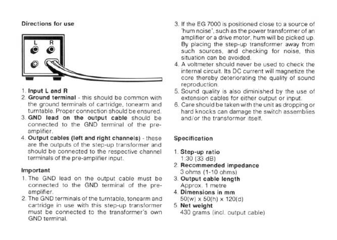
. lnput L and i!

. Ground terminal ~ this should be common with
the ground terminals of cartridge. tonearm and
turntable. Proper connection should be ensured.

3. If the E6 7000 is positioned close to a source of

hum noise'. such as the power transformer of an
amplifier or a drive motor. hum will be picked up.
By placing the step-up transformer away from
such sources. and checking for noise, this
situation can be avoided.

. A voltmeter should never be used to check the

internal circuit. lts DC Current will magnetize the
core thereby deteriorating the quality of sound
reproduction.

. Sound quality is also diminished by the use of

extension cables for either output or input.

. Care should be taken with the unit as dropping or

hard knocks can damage the switch assemblies

3. GND lead on the output cable should be and/or the transformer itself.
connected to the GND terminal of the pre-
amplifier

4. Output cablas (left and right channels) - these
are the outputs of the step-up transformer and
should be connected to the respective channel

terminals of the pre-amplilier input,

Specification

1, Step-up ratio
1:30 (33 d8)
2. Recommended impedance
3 ohms (1-10 ohms)
3. Output cable length
Approx. 1 metre
4. Olmeneiona in mm
50(w) x 50(h) x 120(d)
5. Net weight
430 grams (incl. output cable)

Important

1 The GND lead on the output cable must be
connected to the GND terminal of the pre-
amplifier.

2. The GND terminals of the turntable. tonearm and
cartridge in use with this step-up transformer
must be connected to the transformers own
GND terminal.

Page 2

Features

Selected core material

At the heart of the ES 7000. is an 'L'-shaped core
which is made from carefully selected. cold-rolled
and annealed sheets of European super permalloy
(with 80% Ni). Minimum eddy current loss has been
achieved through two different thicknesses which
are laminated for maximum permeability in the core.
The result is richly extended low notes. a soft and
clear middle range and a smoothly defined range of
high notes.

Ingenious winding method

The PHILIPS EG 7000 features an ingenious wind-
ing method - the multi-split and interlock system. in
which primary and secondary windings are split out
into several elements and interlocked with each
other - thus minimising stray capacitance and
leakage inductance.

Conventionally. the winding for the low input is a
small section of the input windings for the higher
impedance cartridges. Because of possible leak-
age inductance. results are not always satisfactory
with low impedance cartridges.

in the EG 7000 however. the primary windings tor
the low impedance input are also split out into each
element. thus solving the problem and at the same
time. achieving superior sound characteristics.

Litz wire for internal wiring

Litz wire is used for the internal wiring of HF test
instruments. It avoids undesirable skin~effects in
the high frequency ranges. and at the same time
minimizes possible sound distortion. giving a supe-
rior clarity to the high notes.

Extra low capacitance and noise-free cables for the
output connection

Extra low capacitance has been achieved by using
litz wires. and lapping the shield wires laterally
around the central cable core. Both are sheathed in
a conductive carbon texture tube under the ex-
ternal insulation.

This technique protects the cable from possible
mic rophonic noise caused by shock and/or sudden
deformation to the cable during use.

Protection from distortion

Aluminium has been selected for the case and
chassis to avoid the possibility of magnetic distor-
tion which sometimes occurs with steel cased
units.

Gold-plated input and output terminals are fitted to
provide better control of the sensitive MC canridge
signals through their low contact potential differ-
ence.

For all internal soldering. a lead/tin/copper solder is
used because of its beneficial effects on sound

quality.