Philips dvdr 70 75 service manual

This is the 260 pages manual for philips dvdr 70 75 service manual.
Read or download the pdf for free. If you want to contribute, please upload pdfs to audioservicemanuals.wetransfer.com.

Page: 1 / 260
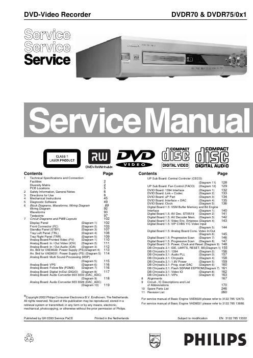
philips dvdr 70 75 service manual

Extracted text from philips dvdr 70 75 service manual (Ocr-read)


Page 2

Technical Specifications and Connection Facilities EN 3 DVDR70 & DVDR75/0x1 1. 1.3 General: Mains voltage : 198V-276V Mains frequency : 43 Hz - 63Hz Power consumption mains : 28 W Power consumption standby : < 7 W Power consumption low power stand-by : < 3 W 1.4 RF Tuner Test equipment:Fluke 54200 TV Signal generator Test streams:PAL BG Philips Standard test pattern 1.4.1 System: PAL B/G, PAL D/K, SECAM L/L, PAL I 1.4.2 RF - Loop Through: Frequency range : 45 MHz - 860 MHz G a i n : ( A N T I N - A N T O U T ) : - 6 d B t o 0 d B 1.4.3 Radio Interference: input voltage /3 tone method (+40 dB min) : no limit 1.4.4 Receiver: PLL tuning with AFC for optimum reception Frequency range: : 45.25 MHz - 857 MHz Sensitivity a t 40 dB S/N :≥ 60dBµV at 75Ω (video unweighted ) 1.4.5 Video Performance: Channel 25 / 503,25 MHz, Test pattern: PAL BG PHILIPS standard test pattern, RF Level 74 dBV Measured on SCART 1 Frequency response: : 0 - 4.00 MHz +0-4dB Group delay ( 0.1 MHz - 4.4 MHz ) : 0 nsec ± 150nsec 1.4.6 Audio Performance: Audio Performance Analogue - HiFi: Frequency response at SCART 1 (L+R) output: : 100 Hz - 12 kHz / 0± 3dB S/N according to DIN 45405, 7, 1967 : and PHILIPS standard test pattern video signal: : FM: ≥ 50dB; AM ≥ 45dB, unweighted Harmonic distortion ( 1 kHz, ± 25 kHz deviation ): : FM ≤ 1.5%; AM ≤ 2% Audio Performance NICAM:Frequency response at SCART 1(L+R) output: : 40 Hz - 15 kHz 0 ± 3dB S/N according to DIN 45405, 7, 1967 : and PHILIPS standard test pattern video signal: : ≥ 60 dB unweighted Harmonic distortion (1 kHz): : ≤ 0.5 % 1.4.7 Tuning Automatic Search Tuningscanning time without antenna : typ. 3 min. PAL stop level (vision carrier) : ≥ 37dBµV Maximum tuning error of a recalled program :± 62.5 kHz Maximum tuning error during operation :± 100 kHz Tuning Principle automatic B,G, I, DK and L/Ldetection manual selection in "STORE" mode 1.5 Analogue Inputs 1.5.1 SCART 1 (Connected to TV) Pin Signals: 1 - Audio R 1.8V RMS  2 - Audio R  3 - Audio L 1.8V RMS  4 - Audio GND  5 - Blue/Chroma GND  6 - Audio L  7 - Blue out/ Chroma in 0.7Vpp ± 0.1V into 75 Ohm (*)  8 - Function switch <2V = TV >4.5V / <7V = asp. ratio 16:9 DVD >9.5V / <12V = asp. ratio 4:3 DVD  9 - Green GND  10 - P50 control  11 - Green 0.7Vpp ± 0.1V into 75 Ohm (*) 12 - Nc 13 - Red/Chroma GND  14 - fast switch GND  15 - Red out/ Chroma out 0.7Vpp ± 0.1V into 75 Ohm (*) ± 3dB 0.3Vpp Chroma (burst)  16 - fast switch RGB/ CVBS or Y <0.4V into 75 Ohm = CVBS >1V / <3V into 75 Ohm = RGB  17 - Y/CVBS GND OUT  18 - Y/CVBS GND IN  19 - CVBS/Y 1Vpp ± 0.1V into 75 Ohm (*)  20 - CVBS/Y  21 - Shield  1.5.2 SCART 2 (Connected to AUX) Pin Signals: 1 -Audio R 1.8V RMS  2 -Audio R  3 -Audio L 1.8V RMS  4 -Audio GND  5 -Blue/Chroma GND  6 -Audio L  7 -Blue in/ Chroma out ± 3dB 0.3Vpp Chroma (burst)  8 -Function switch  9 -Green GND  10 -P50 control  11 -Green  12 -Nc 13 -Red/Chroma GND  14 -fast switch GND  15 -Red in/ Chroma in 