Philips bx 732 a
This is the 16 pages manual for philips bx 732 a.
Read or download the pdf for free. If you want to contribute, please upload pdfs to audioservicemanuals.wetransfer.com.
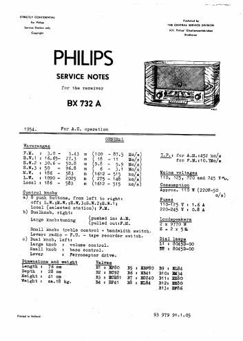
Extracted text from philips bx 732 a (Ocr-read)
Page 2
-2-
A.
BX 732 A
DESCRIPTION OF CIRCUIT
FJI. Section
B.
The signal arriving via the dipole aerial is fed to the balanced
input circuit $52-852'-C10-C11 and S10. Coil S10 is inductively cou-
pled to $11 which is in the grid circuit of B1. Together with the
wiring capacitance and the input Capacitance of 31, S11 forms a tuned
circuit which resonates in the middle of the band, Le. 93 Mo/s.Ths
tuned anode circuit of B1 is made up of 312-512' and 020. 132 functions
as mixer. The oscillator circuit consists of an inductive feedback
circuit 513-513' and 314-514'.
The serial signal amplified by B1 is injected via 615 into the oscil-
lator, so that across the 1st LF'. band-pass filter (515-022 and
5164124) there appears an LP. signal with a centre frequency of
10.7 lie/s.
The heptode section of B3 functions as amplifier; the triode section
is rendered inoperative due to the grid being short-circuited.
The second LF. bandepass filter is formed by the tuned circuits
553-073 and 554-074. The third stage comprises B4 and the third band-
pass filter 561-691 and 562-692. After further amplification in B5
the signal is fed to the discriminator.
As detector 5 ratio detector is used so that no separate limiting
stage is needed. The electrolytic capacitorc117 functions as limiter.
The LP. signal appearing across C115 is fed via the volume control
251-152 to the control grid of BT.
Adi. Section
Apart from the normal NLW. hand, this receiver has a second M.W.
range. This has its own set of coils (319-520 and 529-330) and a
separate Z-geng variable capacitor ((240-041). This capacitor can be
adjusted to a desired station (mainly a local station) by means of a
knob located at the back of the set. By pressing in the station se-
lector push button, the station is received without having to make
use of the normal tuning knob.
On all bands except ILW. and L.W., the serial signal is coupled in-
ductively to g133 as follows!
selected station hand x vie $19-$20
S.W. bends 1,2 and 3 x vie $21-$22; 323-824
and 525-826 respectively.
On the M~Wo end L.W. bands the aerial signal is fed via 31! and S18 to
311313. Coils S17 and 318 are mounted on a rotatable ferroxcube rod.
This combination, the Ferroceptor, possesses the properties of a loop
aerial which can be connected in circuit by means of a switch.
The amplified aerial signal is fed vie $27 or S28 in the anode cir-
cuit of 1313 to the control grid. of the mixer (BB).