Philips bx 307 u

This is the 13 pages manual for philips bx 307 u.
Read or download the pdf for free. If you want to contribute, please upload pdfs to audioservicemanuals.wetransfer.com.

Page: 1 / 13
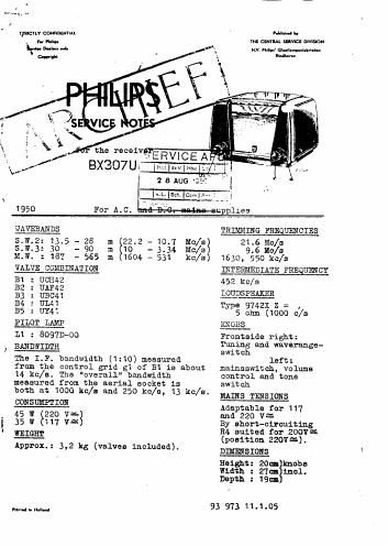
philips bx 307 u

Extracted text from philips bx 307 u (Ocr-read)


Page 2

-2- BX 307 U
MORTANT

When repairing or trimming a not while it is connected to -
LC. mains, a transformer has to be used with separate
windings. The secondary winding must not be earthed, and

only one set may be connected to the transformer at a time.
The chassis can then be earthed. The codenumber of a suitsblo
type of transformer is given in the Imist of Parts and Toola'.
When connecting the set to TLC. mains the connection must he
made with the right polarity.

SOME PARTICULARS ABOUT THE PRINCIPLE DIAGRAM

This set has been provided with a frame-aerial, which is
very effective on S.W.3 and M.W., while there is a capacitive
aerial for the 8.12 band. When an outdoor-aerial is used,
both antennas remain connected to their circuits.

1:339.sz '
For trimming the LF. part the set need not be uzxcesed but
the screening plate, which covers the H.F. part, has to be
removed. The oscillator frequency is higher than the Sign].
frequency.

A. I. F. BANDFILTERS

1. Volume control to maximum.

2. Variable condenser to :31.an capacity.

3. Earth chassis, taking into account the remarks above
under Important.

4. Connect outpx meter via trimming transformer to loud-

speaker com; ions.

Apply LY. Signal of 452 hc/s via a 35000 p? condenser

to $1 of Bi.

Loosen the screws on the LP. transformers.

Trim successive I maximum output the 4th, 3rd, 151:

and 2nd I.F. c (see fig-.7).

Seal the screws . 1th sealing compound.

m

ELF. AND OSCILLATOR CIRCUITS

Volume control to maximum. Earth the chassis taking into

account the remarks under "Important".

Connect outputmeter vis trimming transformer to

loudspeaker connections.

Turn the variable condenser on minimum, adjust the

pointer to the zeropoint on the dial. If necessary un-

screw the fixing screw on. the pointer and readjust the

position of the pointer.

4.. Wave range switch on M.W. and apply now a signal of
1630 kc/e.

5. Trim at maximum output 021 and C11.

6. Pointer on trimming point at 550 kc/s, apply a modulated

signal of 550 kc/s to the aerial socket via. the dummy

serial.

7. Trim at maximum output C18.

8. Waverangeswitch at s.w.3.
Apply modulated signal of 9.6 Mc/s to the aerial socket
via the dummy aerial. Tune the set on this frequency.

sandman-10