Philips bx 297 u
This is the 16 pages manual for philips bx 297 u.
Read or download the pdf for free. If you want to contribute, please upload pdfs to audioservicemanuals.wetransfer.com.
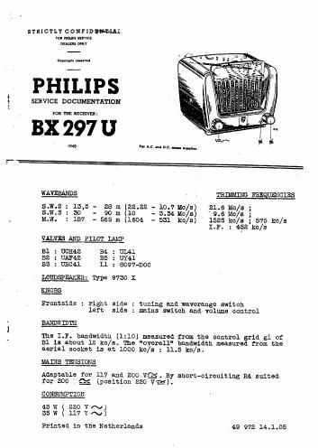
Extracted text from philips bx 297 u (Ocr-read)
Page 2
-g. Ex 29%
DMSIONS
He ight : 21
Width : 26,5 cs;
Depth : 18 cm)
WEIGHT: Approx. : :5 kg. (valves included)
DJPORTAN'E
when repairing or trimming a set while it is connected to 3.0.
mains, a transfer-v": has to oe used with separate windings. me
secondary winding must not be eerthed while only one set may be
connected to the transformer at a time. The chassis can then be
earthed. me code number or a suitable type of transformer is
given in the "List of Parts and Tools". When connecting the set
to D.C. mains the connection must be made with the right polarity.
SOME PARTICUTLARS ABOUT TdE PRINCIPLE DIAGRAJL
This set has been provided with e rrameeerial which is very
effective on 11.. , while there is a capacitive aerial for the
SJI. hands. When en outdoor aerial is used, both antennas remain
connected to their circuits. If no outdoor-aerial is connected
and thus the built-in frame-aerial on MM. is used, 055 is
switched pereliel to 06. This to compensate the influence of the
outdoor-aerial capacity.
THINKING
For trimming the set need not be uncesed.
Only the rear panel and the screening plate, which covers the R.F.
pert,'hsve to be removed. The letter can be pulled out between
the side of the chassis and the cabinet.
The oscillator frequency is higher than the signal frequency.
A. I.F. WEFILTERS
1. Volume control to maximum.
2. Variable condenser to minimum capacity
3. Earth chassis, tennis into account the remarks above under
"Important" .
4. connect outputmeter via trimming transformer to loudspeaker
connections.
5. Apply LE. signal of about 452 kc/s via. a 55000 pii condenser
to 31 of 32.
6. Determine the twine, of the 5rd and 4th Li. circuit.
'7. Apply this signal to the control grid .3]. 01 31 via a condens-
er of 53000 p2 and turn the cores of the let and. anti LE.
circuit as far out as possible.
6. Trim successively to maximum output the let and and LE.
circuit.
9. Seal the cores.
REMARK
The iron cores or the I. . benefilter are sealed with"vaseline
compound" (for code nuczber see "List of Parts and Tools"). This
compound does not require heating for making adjustments, because
it. can be removed in the cold state with a screw-driver.
HEATING 0F TEE CORE?» DAMAGES TEE COREHOIDER AND mas ADJJSflEITT
IMPOSSIBLE,-
v