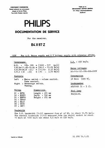
Philips b 4 x 67 z service manual
This is the 13 pages manual for philips b 4 x 67 z service manual.
Read or download the pdf for free. If you want to contribute, please upload pdfs to audioservicemanuals.wetransfer.com.
Extracted text from philips b 4 x 67 z service manual (Ocr-read)
Page 2
-2- 34x6'lZ
TRIM); m RECEIVER
For all circuits the following applies:
Volume control to maximum.
'lone oontml at "quality".
Connect a voltmeter via. a trimming transformer to the extension
loudspeaker sockets.
Unless otherwise stated all signals are applied to the serial
sooket via a dummy serial.
Adjust the pointer at trimming point 1 (variable capacitor at minimum).
Seal the cores and trimmers after the alignment.
Weverenge Pointer at Apply s mo- lrim for
switch at trimming point dnlsted signal maximum
V or output
I.F.bend- mw. 1 452 kc/s to g1 524,523,
filters of 32 vie $21,522,
33000 M 523
MM. 2 550 ko/s $20,511,;
38s re-
Geng cep.min. 1630ko/s 036,08, )peet
V (:10 )
m". S.W.2a 2 14.51Mc/s a31s )
circuits 19 max.
. 39-55 re~
Gang eepnnin. 26.5Mc/s G34 99""
1e max.
016, 08
s.w.2b 2 12.2 Mc/e 029
Tune the set 11.8 "0/5 620,012
2 3.36 Mc/s 518,310,)
S.W.3 S1
re~
peat
Gang osp.min. 10.1an/s 035,017}
09
Before starting to trim 315-034 should be unscrewed and 59-016 screwed.
in as tax- es possible.
REPAIRS AND REPLACEMENT 0F PARTS
Taking the chassis from the cabinet.
1. Set the variable capacitor to maximum capacity.
2. Remove the r'esr panel.
3. Unsolder the loudspeaker connections.
4. Remove the knobs.
5. Remove the scale pointer from theoable.
6. Unscrew the two chassis-fixing bolts and take the chassis carefully
out of the cabinet.
Replacing of the dial
1. Take the chassis out of the cabinet.
2. Remove the two dial-fixing clips.