Philips az 8390 service manual

This is the 18 pages manual for philips az 8390 service manual.
Read or download the pdf for free. If you want to contribute, please upload pdfs to audioservicemanuals.wetransfer.com.

Page: 1 / 18
philips az 8390 service manual

Extracted text from philips az 8390 service manual (Ocr-read)


Page 1

CD Stereo Radio Recorder AZ8390/00/008/o7/07s
/1 0/1 08/1 7

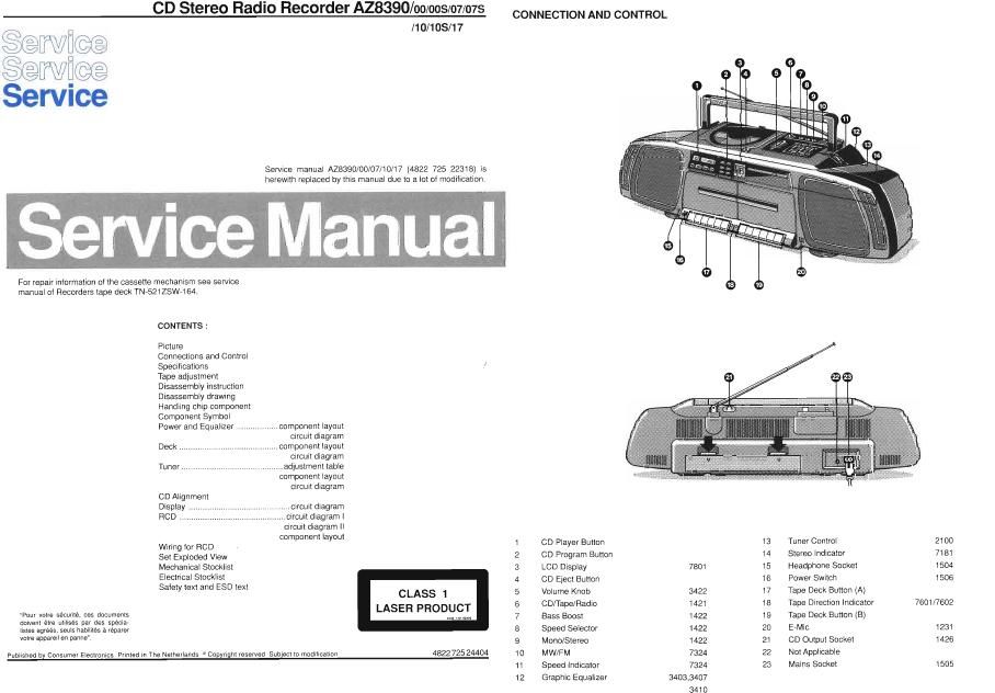
CONNECTION AND CONTROL

1 \//W\QE.\

\J

Service manual A28390/00/07/10/17 (4822 725 22318) is
herewith replaced by this manual due to a lot of modification.

For repair information of the cassette mechanism see service
manual of Recorders tape deck TN-521ZSW-164.

CONTENTS :

Picture
Connections and Control

Specifications .1
Tape adjustment

Disassembly instruction

Disassembly drawing

Handling chip component

Component Symbol
Power and Equalizer .

7 component layout
circuit diagram

Deck ........................................... component layout
crrcurt diagram
Tuner ............................................ adjustment table

component layout
circurt diagram

CD Alignment
Display
RCD ..

.circuit diagram
circuit diagram 1

circuit diagram ll
component layout

Wiring tor RCD 1 CD Player Button 13 Tuner Control 2100
Set Exploded View 2 CD Program Button 14 Stereo Indicator 7181
Mechanical Stocklist 3 LCD Display 7801 15 Headphone Socket 1504
E'eCi'ica' 50051 4 CD Eject Button 16 Power Switch 1505
Safety text and ESD text CLASS 1 5 Volume Knob 3422 17 Tape Deck Button (A)
6 CD/l'a e/Radio 1421 18 Ta e Direction Indicator 7601/7602
Pour votre sécurité, 095 documents LASER PRODUCT 7 Bass Bpoost 1422 19 Tage Deck Button (B)
doivent étre utilises par des specia-
Iistes agrees, seuls habilités a réparer 8 Speed Selector 1422 20 E-MlC 1231
m" We" 9" am 9 Mono/Stereo 1422 21 CD Output Socket 1426
Published by Consumer Electronics Printed in The Netherlands 5 Copyright reserved Subject to modification 4822 725 24404 10 MW/FM 7324 22 Not Applicable
11 Speed Indicator 7324 23 Mains Socket 1505
12 Graphic Equalizer 3403,3407

3410

Page 2

SPECIFICATION

GENERAL
Mains voltage
Mains selection/setting

Battery

Mains frequency
Power consumption
Dimension (W x D x H)
Weight

TUNER: FM SECTION

Tuning range

IF frequency

Sensitivity at 26:18 S/N
Selectivity at GOOKHZ bandwidth
IF rejection

Image rejection

TUNER :AM SECTION
Tuning range

IF frequency

Sensitivity at 26dB S/N
Selectivity at 18kHz bandwidth
lF rejection

Image rejection

AMPLIFIER

Output power at 10% distortion: Mains
Battery

Speaker impedance

Frequency response within 3.5dB

Equalizer control

Bass boost switch

Lineout sensitivtty

Headphone output at 329

CASSETTE RECORDER

Number of tracks

Tape speed

Wow and flutter

Fast-wind time 060

Bias system: AM
Others

Recording playback frequency response within esdB

Signal to Notse ratio: AM rec
FM/CD

Dubbing

COMPACT DISC

Frequency response within +2dB/e4dB
Signal/Hiss ratio

Distortion at 1kHz

Channel difference at 1kHz

Channel crosstalk at 1kHz
De-emphasis

Note : /008 = IOO except production by third party

/078 = /07 except production by third party
/1 OS = /10 except production by third party

PCS 62 849

120V - 220V - 240V
Serviceable
set at 120V 407/17
set at 220V -/00
set at 240V -/10
12V (R20 X 8)
50Hz - eon
38W max.
660 x 183 x 178mm
5.5kg

87.5MHZ ~108MHZ
10.7MH2

< 6pV

> 20dB

> SOdB

> 20dB

526.5kHZ - 1606.5kHZ
468KHZ

< 2.5mV/M

> 16dB

> SOdB

> 2BdB

2 x 4.0W -1dB

2 x 4W -1dB

2 x 59 with piezo
100Hz - 8kHz
-6dB to +SdB
GdB at 100Hz
BOOmV at iOkQ
13mW

2 x 2 stereo

4.76 cm/sec t 2%
2 x 4.76 cm/sec

< 0.35%

130 sec

DC bias

70kHz : 15kl-iz
250Hz , 2kHz (AM)
250Hz 7 8.3kHz (Others)
> 22GB

> 40GB

> 37GB

20Hz , 20kHz

> 80dB

< 0.5%

< 2GB

50dB

O or 15/50 uS (Switched by subcode on the disc)

DISASSEMBLY INSTRUCTION (See Disassembly Drawing)

Front Cabinet Assembly
Place set face downward and remove 10 screws D3 x 45
Remove Front cabinet assembly

Top Panel assembly/CD door assembly
» Uncatch handle P05, 453 as indicated
» Remove 4 screws D3 x 12

- Eject CD door assembly and remove Top panel assembly/CD door assembly

Tuner assembly

Remove 2 screws D3 x 12
Tuner assembly is removed as indicated
- Care must be taken not to damage level Pos. 459 during assembly or disassembly

RCD assembly

RCD assembly is removed by sliding out as indicated
Care must be taken not to damage the pins during disassembly
, During assembly ensure the pins are properly connected to Socket S1

TAPE DECK ADJUSTMENT

Recorder positron MEASURE ADJUST ADJUST
ADJUSTMENT CASSETTE SK. . DECK | DECK ll ON READ ON WITH TO
Left hand
Tape. Play - 1504 mV-meter screw
Azimuth 10KHz Play head Max.
580 420 Left hand
Tape. . Play 1504 mV-meter screw
RIP head L : R
Wow and _
Motor Tape. Play - 1504 Flutter preset 'n . *
speed 3150Hz meter motor a
(Normal) SEC 420* Wow and
Tape. - Play 1504 Flutter -
meter
Motor Tape.
speed 3150Hz HSD Record Play 1504 Frequency 6.0KHz
(high) 530 420 counter : oskHz

A.

SEC 420 : 4822 397 30071

The maxtmum permissible speed deviation is 1%.
Moreover, the wow and flutter value can be read.
This value should not exceed 0.30%.