Philips ah 180 owners manual

This is the 4 pages manual for philips ah 180 owners manual.
Read or download the pdf for free. If you want to contribute, please upload pdfs to audioservicemanuals.wetransfer.com.

Page: 1 / 4
philips ah 180 owners manual

Extracted text from philips ah 180 owners manual (Ocr-read)


Page 2

EngHsh
Nededands
FrangaS
Deumch
Espafiol
Hafiano
Dansk
Norsk
Svenska

Suomi

page 2

pagina 6

page 11

Seite 15

pagina 20

pagina 24

side 29

side 33

sida 37

sivut 41

EngHsh
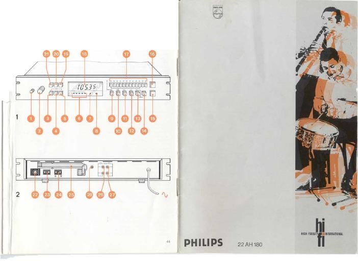
Controls, etc. (fig. 1)

f mains switch 'ON/STAND-BY
output level control
I, muting switch ON/OFF'
,: muting level selector
3 A F-switch
,. signal strength indication 'SIGNAL'
: local FM-station indicator LOCAL'
{4 stereo indicator STEREO
a store button STORE with indicator
w key-in button 'KEY~|N
VI lock switch LOCK'
1;: search switch 'SEARCH'
i} 50/100 kHz selector
i5 wave range selector 'AM/FM'
,. tuning down button 'DOWN'
11 tuning up button UP'
entry/preset buttons with indicators 'AM/FM
MEMORY'
nrsT 1,2. 3, 4, 5, 6, 7, a, 9, 10(= 0)forentering
ms. 1, 2. 3, 4. 5, 6, 7, B, 9. 10, 11, 12 for
presetting
v frequency display
2 stereo only switch 'STEREO ONLY'
'5, mode switch 'MODE
L," MPX-filter switch

inputs, outputs, etc (fig. 2)

inputs FM aerial, 75 ohm

inputs FM aerial. 300 ohm

x-v inputs AM aerial and earth

v ~ AM-rod aerial

" outputs to (ore-)amplifier, FIXED'

outputs to (pre-)amplifier, 'VARlABLE
® Input for switch unit

Checking the mains voltage

Before connecting the set to the mains supply
check that the operating voltage. indicated on the

type plate at the rear, is that of your local mains
voltage. If it is not. do not connect the set to the ,
mains but consult your dealer,

Note [or users in Great Britain

When fitting a mains plug to the mains lead,
please proceed as follows:

The wires in the mains lead are coloured in
accordance with the following code:

blue - neutral; brown - live.

As these colours may not correspond with the
colour markings identifying the terminals In your 1

plug proceed as follows:

The brown wire must be connected to the ter-
minal which is marked with the letter L or colour-
ed red. The blue wire must be connected to the
terminal which is marked with the letter N or
coloured black. This apparatus must be protect-
ed by a 3 amp. fuse if a 13 amp. plug is used or if
any other type of plug is used by a 5 amp. fuse
either in the plug or adapter or at the distribution
board. It in doubt consult a qualified electrician

Connections

Pro-amplifier or integrated amplifier

A pre-amplitier or an integrated amplifier can be
connected to the outputs @ or @,

The output level from sockets @, marked
FIXED, is not adjustable. The output level from
sockets @, marked 'VARIABLE' can be adjusted
with level control ® enabling the output level of
the tuner to be matched to that of other sound
sources connected to the amplifier. Connect the
left and right channel of the amplifier to the
desired outputs ® or @. marked LEFT' and
RIGHT'.

AM-aerlals

The ferrite rod aerial @ will provide satisfactory
reception of local stations with strong signals.
Because this aerial has directional properties, its
direction should be adjusted for the best
reception (se paragraph: Aerial signal indi-
cators'.)

In fringe areas, or in locations surrounded by
steel frame buildings where satisfactory
reception cannot be obtained with the rod aerial,
an AM-outdoor aerial should be connected to the
AM-terminal @, Y-side. An earth lead may be
connected to the other terminal. e-side (see fig,
2).

The rod aerial ® should still be directed for
optimum reception even when using an AM-
outdoor aerial.

FM-aerials

Broadcasts from local FM~stations can be
received using the provisional wire aerial (sup-
plied), which should be connected to the aerial
inputs @, marked 300 Ohm. This aerial should
be positioned to give optimum reception. For best
results, particularly in the case of stereo
reception, an external aerial should be employed,
Dependent on the type of aerial being used (75
Ohm or 3000hm) it should be connected either to
the terminals ® or @.

Aerial signal indicators

The relative strength of an AM/FM signal being
received is shown by five separate indicators .,
The stronger the signal, the more indicators will
light. The optimum tuning point may be found by
tuning the set until the last indicator to light
reaches its maximum brightness. When receiving
very strong signals, for instance, from a local
station. an attenuation circuit is automatically
switched on and indicator ® LOCAL will light.
This indication applies only to FM-stations, When
receiving an FM-stereo transmission, indicator
'STEREO will light. This will remain lit if mods
switch @ is set to MONO' position.

Switching on / stand-by

Depressing switch ® switches on the tuner and
the display .will light, showing the frequency of
the station to which the set was tuned when last
switched off, Setting switch ® to position
'stand-by' (not-depressed) switches off the tuner
so that only the memory circuit is still energized.
The information stored in the memory circuits is
thus retained.

Note: Should the mains supply be disconnected
for a period in excess of approximately two days,
the stored information will be lost and the memory
circuits will require re-programming.

Muting of weak FM-stations

Depressing the muting on/off switch ®
eliminates the undesirable interstation and weak
station noises inherent to the FM-bend, The mut-
ing level can be chosen by setting muting level
selector ® to either position '1' (not depressed)
or 2' (depressed),

Muting switch @ should be set to position 'OFF
(not depressed) to permit reception of a weak
station.

Muting of a detuned FM-station

Using the possibilities of the built-in synthesizer
system, depressing the A F switch ©enables the
checking of the tuning accuracy of an FM-station
being received. Based on the 50 kHz catch range
of the synthesizer, every FM-station which is 50
kHz (or more) away from the tuned frequency, will
be muted. This is a valuable aid when checking to
see if an FM-station is accurately tuned to the
centre of an FM-channel (zero»axis cross-
ing'). If it is not, the station will be muted when
depressing the A F-switch. In this case, the set