Philips 838 u schematic

This is the 2 pages manual for philips 838 u schematic.
Read or download the pdf for free. If you want to contribute, please upload pdfs to audioservicemanuals.wetransfer.com.

Page: 1 / 2
philips 838 u schematic

Extracted text from philips 838 u schematic (Ocr-read)


Page 1

November, 1935

COSSOR 368 MAINS
THREE ' (Cont)
Mains equipment consists of : Tr former,
442 BU rectifier, speaker field in the posir
iiVe H.T. lead, and electrolytic condensers,
The pilot lamps are 6.5 v. ,3 amp. type.
Quick Tests. 777 Voltagns between

the

terminals on the speaker transformer and
chassis, counting from the outside :-
(1) Blue, FLT. unsnloothed, 340 v,;

_ 8%

Red, V3 anode, 230 v.; I
and (4) Yellow, H.T. smoothed, 240 v.


Service Engineer Supplement to The Broadcaster

Removing Chassis.-Remove the knobs
(grub screw), undo the speaker leads from
the speaker transformer, release the mains

VALVE READINGS

Nu Signal. Volume control at maximum,
Valve. Type. Electrode. Volts. no
1 MVS Pen. nlet nilode .. 21.5 2
7 aux. grid .. 120 1
2 MS lenr met. node 55 LS
(7) MIX. grid . 4 35 .4
3 H MP (5) anode 230 so

91

cable from the cleat, remove the holding
screws from underneath and lift the chassis
outr

General Notes.-Of the three leads from
the condenser block, red is 018, white is 017
and black is common negative.

This willing and lay-out of this set are par-
tiulilarl simple. and all the components are
l'iiilllly an: .sible,

Replacing Chassis. ~ Lay the chassis
lllSlilL the cabinet, replace the holding screws
and knobs, client the mains lead and re»
connect the speaker lends ill the some order.

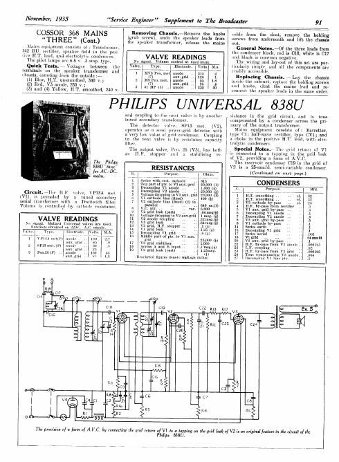
PHILIPS UNIVERSAL 838U

luld coupling to Hie next valve is by another sistance in the grid circuit, and is tone
tuned secondary transformer. compensated by a condenser across the pilr
The detector mire, 8PM met. (V2). "law. of the PW "asimmer'
uperatcs us a. semi powcrrgrid detector with Na? equlpmeiit consists 0f: Barrettel,
a very low value of grid condenser. Coupling WI? ('13. half-wave :lECtlfieI', WPe C¥13 and
to the next valve is bv resistance capacity 101, 1 the 105? H-T- lead, w 9199'
filter. ' irolytlc condense
The output valve, Poll. 26 (VS), has both . Special: drift t T"? W? gluingfivfi
on H,Fl 510 or and :t staliilisillv re» '3 conlece , .° 5 applllg_lil e gri ea
pp A of V2, prov1d1ng a. form oi A.V.C.
The Philips The reservoir condenser 019 in the grid of
333U1hm RESISTANCFS V2 is a 25-mmfd. semi-variable condenser.
fur_AC.-DC R we 01th (Continued on next page.)
mains. - 7 __ .. ,A .
1 . s with root. cathode . 315
2 Top part ofptr. to v1 aux grid 20,000 (I) CONDENSERS
s gecoupllng V; image .. $60336) C. Pun i
. H . . 4 econ ing ' one o ., , ( _ w
Circuit-"11w ILL \uhe, \'P15A mel- 5 VoltaggdroppingtoVs aux. grid 20,000 (i) 1 HI. smoothing
(V1), is preceded by :1 tuned secondary is ill 2'13? iii (gills?) (2) .. 400m 2 géTlifingthing
.- .. - . .. , 7 'cu ensxe in a caoeyass
'{fflal LIWSOmmnw'nl) . d. Dmlnwmh- fuel; parallel .. .. ., 640 mu) 4 In. by-pdss from xertifier
o nmo ls cantm ail y natlioi c resls ancL, 8 vs. NF- .. var. I 5 V1 aux, grid hy-pass ,.
1) V2 grid leak (put) .. .. .64 meg) 6 Decoupling V1 anode ,.
10 Voltage dropping to V2 nux.grid 1 meg. (i) 7 Decoupling V2 anode ..
VALVE READINGS 11 V2 anode coupling .. .. 321mg) 8 V3 aux. grid bypass
. . 12 v3 grid look .. .. .64 meg) 9 V1 cathode by-puss
in slgnnl. Mulidrd Universal values are used. 13 \73 grid. HF. stopper .. '1 14 Sum emu, ,.
9W WNW 0 0 M" WWW- V1 grid leak ., 1.25 (g) 15 Decoupling v1 grid
pr. 1 Minnie. {in s, ,\i.A. 15 Decoupling V1 grid .. .8 (l) 17 Series aerial ..
7 . , . . , 7 , ~~ in Middle part of ptr. to V1 in 18 ,.
1 Vllim niciu') Hlmlli' 12w grid .. ,. .. 25.000 (l) 20 V2 aux. grid by-poss .1
aux. urill .. 17 V3 grid stabilisor .. 1,000 21 H by-pass from .
2 SP13IHOLU) muuio 16 Across A and E input .. mail) 22 coupling . . 2
aux. gllvl .. 19 V2 grid leak (part) 1.25meg, 23 1-1, bypass from i r, .
:i Pen,26(l) anode (l) :4 Tone compensating V allude .001
mlx.griil .. Bun-men figures denote wattage rating. I 27 Decoupling Vi hills mi. .5
E A
ms
CI7
CM 00 E 0?;
CI9 czz m3 .7 E Ex. 5
I C28 4|- v2 4 R V3
'r .
JG (So o
25 . == ==
h c , n c 4
1 2' .
5 c czo
4 I}
C R R
26 ,3 lo

csT

T 41*

I l g aim

d: c7

kl

==

000

m

oo>-o .

0

The provision of a form 0/ A.V.C. by connecting [he grill return of VI la a lapping an the grill leak

Philips 838U.

a] V2 is an original feature in the circuit of the