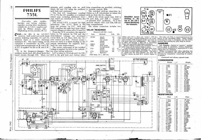
Philips 735 l service manual

This is the 2 pages manual for philips 735 l service manual.
Read or download the pdf for free. If you want to contribute, please mail your pdfs to info@audioservicemanuals.com.

Page: 1 / 2
left right
philips 735 l service manual

Extracted text from philips 735 l service manual (Ocr-read)


Page 2

Radio Marketing Service Engineer May. 1942

vi

There

Switch M.W.

condenser.

grid with anode reaction coils. to Inject -
are trimmers and padders for both bands 452 kc. via .1 mfd. to Vl grid (i.e., H I] W l [TUNE I [R12 | pale:
in this stage. The band-pass section has across centre section of gang).
. trimmers for M.W. only, these being on Adjusttthe four I.F. trimmers for peak
EVER READY the gang condenser. on an output meter, keeping the signal T2 .
R6 and R7 modify the feed-back and always its low as possible to prevent f h
5 I 0 4 give more stable results. operation of the A.V.C. ' Haw! o t 9 top T4 .
. Trimmer-tuned intermediate-frequency M.W. Bani-This band should be o 915V 3:?
transformer link up V2, the I.F. amplifier, adjusted first. See that pointer registers has: iden ylng T3 .
L I S S E N 3 4 O I and vs, the double-diode output pentode. with 130° line with the gang at maximum. 9 1 "gm and
R11 is the signal diode load with 024 Set Tl approximately twothirds in. m mm-
as the H.F. by-puss end 023 to pass the Tune to 214 ln., inject 214 m. to A and E, '
LF. on to 312, the volume control. The and adjust T2. Then adjust T3 and 14. MT
slider goes to the pentode grid via a Time to 500 m., inject 500 m. and
parasitic oscillation stopper, R10. Bias adjust Tl. _ .. V
Threewalve, plus rectifier, table is provided by R13. Readjust '12, T3 and T4 itt 21st in.
model 814 he! we: two wave_ . The A.V.C. diode is fed by C25 and L.W. Band.fSet T5 approximatdy
1) fly the control voltage ls developed across threequarters ln. Tune to 1,200 m., VALVE READINGS CONDENSERS
bands and for operation from 200- ». , . . o . M d
250 volt A 0 l' M k I d R14 and R15. 1he cathode bias now inject 1,500 m. and adjust T6. V Ty Elmradr Volts Ma 0, Midi. | 0. 1 Is.
E - PP? '1 N acts as A.V.C. delay. It will beseen Tune to 1,700 11]., inject 1,700 m. and _*__Pe_-'___; fll 3*W100mmu
by. W Ready {WW Ltd-r and that V2 is provided with a lower control adjust T5. 1 A3613 Anode 2.10 1.7 _1 25 10 mm.
Imam, Lido Eley 8 Estate London. voltage than V]. Reudjust T6 at 1,200 m- giieeinoue 16:3 37 i100 ft] 3? 5:05
N.18. There are a fixed tone corrector, 027, WINDINGS Cathode 149 124 11 :: 3002201: 25 ., :01
and a variable adjustment, CZS-Rlfi, in 2 A50P Anode 246 3.3 13 300 mm. 29 . . 3 j
parallel with the output valve. L W i In 2t: Screen 172 1%; 20 .. .1 .30 .. :5
ileum-The aerial is coupled to V1y H.T. is drawn from a full-wave 1 10, 11,12,13 6.7 s A27D 32.53260 213'; 35' 3% " Ii 33 I: 23 filaifi:
the frequencg-ckanger,b bfi bang» rectifier, V4, which uses 1.16, the speaker g i; .. .. 3700low 305531 2543 43.3 23 .05
PMS mums on 0% wave on S- T 9 field and two electrol'tics for smoothin . a 0 e . - .
arrangement is simple with transformers , y g g g {rfgjw 1 A1) Aifid'é" 622 A.C. g HESISTANCES
for the first section and inductive coupling GANGING 6 is $31: Cathode 346 64 R. Ohms R. Ohms
between the coils to the grid circuit. 1 F Circuits -Shgrt circuit the 7 .. '2 ow . - -
. , ~ . f ' ' . 8 , 2 ., . a, .. . 1 417000 9 150
The oscillator section of V1 15 tuned oscillator (front) section of the gang 9 20 36 PM lamp 1 mm 5 5 I 3 mp 2 20,000 10 110.000
12.: 11 2.3.33
12 ,
5 51,000 13 150
0 ' 1,000 ll 200,000
7 5,100 15 260.000
is 25,000 16 50,000
PHlLlPs -Cominued from opposite page
M.W. Band.7'rline to 180 m. Flt special
Cl trimming iii; to rear of spindle and turn back
manuul control until condenser tests analnst jig.
U7 | Alternatively, chock dial position and calibration,
| and see that pointer registers correctly at
maximum or minimum positions of gang.
l Inject modulated 1,600 lrr. signal to serial
I and earth via standard dummy aerial. Adjust
ZOO-ZSOV T1, T2, T3, T2, T1 for maximum on an output
| 40-60" meter. .
V4 Keep Input low to prevent operation of A.V.C.
/ LIB | Remove jlg and inject 540 he. Connect the
i aerial socket of another receiver through
I n 25 lllmfds. to the anode of the mixer section of
'l' I /L20 Vl. Connect the output meter to the additional .
rece ver.
f Tuuc both recciverr to about 550 m. Dis-
l connect uuxiliury set and reconnect output meter
to 735L, Without touching tuning knoh
I adjust Ti ror llmxlmllm.
:0 Rmdillst '1] or. 1.000 kc. (180 ln.).
l_ Instead of this special padding method.
Ll9 I one can gillllfly tune to 550 n... inject 510 kc.
and adj: .
. l l..w. fiend-Trim with T5 at 750 m. (400 kc.)
either in the usual way or by using the additional
I008 ver.
1' Pnd with T6 at 1,875 m. (160 kc.) either in the
urusl why or by usimr the extra set.

Repeiit T5 adjustments.

S.W. BandiThere are no adjustments.

Filter Cumin-Inject to 125 km, tune for
maximum (top of L,W.) and adjust T7 for
minimum.