Philips 730 a service manual 3

This is the 2 pages manual for philips 730 a service manual 3.
Read or download the pdf for free. If you want to contribute, please mail your pdfs to info@audioservicemanuals.com.

Page: 1 / 2
left right
philips 730 a service manual 3

Extracted text from philips 730 a service manual 3 (Ocr-read)


Page 1

7

lllllllllll[llllllllllllilllllllllllllllllllllllll! lll llllllllllllllllllllllllll llllllll lllllllllllllllillllllllllll llllll llllllllll l "Ill! l [l

I

TRADER" SERVICE SHEET

647

hIllllIllillllllllllllll'lllllill l lllllllIllll'illllllllilllllllll llllllllllllllllilllllllHl lll llllllltlllllllilll lllllllllll Illlllllllllllll, l ll

The Philips 730A rcceivu.

\VO RF and three AF Vilves are

employed in the Philips 750A, 3.

5-vnlve (plus rectifier) "Supexia-
Llurtzniije 2-hand receiver designed o
operate honl AC mains of 100260 V,
40100 c/s.

A similar chassis is employed in the
720A, but it is houserl in a moulded calvi-
net and does not include a. speaker or on t-
put transformer.

[fr/ruse Jun: 1931 (bath made/x)

Original prices: 730A, .625 4i.; 720 \,
£17 173,

CIRCUIT DESCRIPTION
Aerial input from Afi via a pro-set con-
dense! 030 and tapping on L1 to Capariy
coupled bandpass filter. Primary co ls
L1, L2 are tuned by 033; secondaries L3,
Ll by 636. Coupling by 61. c3. Inpit
from a second socket A1 is via a toy

Supplement to The Wireless CV
Electrical Trader, November 20, 1943

647

ISHILIPS 730A

AND 720A TRF RECEIVERS

small capacity 01 to A2 socket, 01 con
sisting of the mutual capacity between
the two sockets.

First vzilve (V1, Mullard metallised
S4VB) is an [if telrode operating as
signal frequency amplifier with gain coii~
tml by variable potentiometer R5.

Tuned-anode coupling by L5, L6 anil
639 between V1 and second RF tetrodc
(v2, Mullard metalliaed swn) operating
as Signal frequency amplifier. 01, ca
serve as trucking condensers to keep the
tuiied circuit in step With the band-pass
circuits. It should be nnted the 039 is
isolated from chassis.

Aperiudic tunedraliorle coupling liy L1
(MW) plus 013 [LVW between V2 and
lriode detector valve (V3, Mullen! metal-
Iiseil 244V), operating on Lhe grid leak
system with 014 and R11. Provision for
connection of gramophone pickup in CG
circuit. RF filtering by 011, R19, 015 iii
anode circuit, 'lworposition tone control
by 019, 55 in anode circuit.

Resistance capacity Loupling by R15,
620 and R11 between V3 and second
lriode valve (v4, Mullnrd new), oper-
ating as AF amplifierywith stéprdown
resistance capacity coupling by R19, 011,
023 and R20 to directly heated pentode
Output valve (V5. Munaru PMzzA).
Fixed tone Correction by 025 in anode
circuit Provision for connection of high
impedance external speaker, also in anode
circuit.

HT current is supplied by fullrwave
rectifying valve (VG, Philins 1821).
Smoothing by iron-cored choke LB, in
negative HT lead to chassis, and con
(lensers ms, (:21.

GB potential for V3 (on gram) and VA
is obtained from the drop along R23,


which is in sellei with La, while GB for
V5 is obtained from a tapping on LB, the
control grid circuits being decoupled by
028, 822 {ind 029, R24 respectively.

COMPONENTS AND VALUES

n

CONDENSEKS Values
(wk)
1 Ai-iilil A2 'eu
linniiqinsn l'OHDlllIK
\'1 so ill: mulling
Vl ,zithmlc hy-pztss
v1 Anodi- Decoupling
} v1 :innili, trackers

cc

V2 (1G condenser
v2 coupling
Ivy-puss
nnndlili nupling
lode L ' Shunt
V Uiicomlcnscr

l}v:i anniin decoupling . {

} RF berllSl-i condensers, {
Time Control condenser
w to v4 AF coupling
V i anode docmipilng

}\4 to V5 All cauDlinl .. {
v5 so uni-,nnnllng
Fixed tone correctux

} [{Tsmoothing condensers {
v4 CG uncunpilng .
V5 CG decoupling
Aerial series coupling .

.:eevw9;¢?9$¢¢raw-9990;2cqc-c


H-l' ml. 1. w, triininc

.1er pri. M trimm 0 00002
Blind-pass pr tuning . 0 owns
ll-l sec. liW inimel 0 00001
B-P SL1" MVl' nine 0-00042
Band-p ss se . tuning o-uoaos
\l anode liW'tiimmcl 0 UJUtH

[381 V1 anode MW trimmer 0 00002
0591 \i. anode Liming l) ileum;

l Variable. V-
: Pre-set.

sou UMP

I! M as
.4.-
i l) -

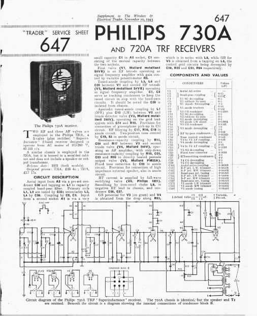
Circuit diagram of the Philips 730A TRF Superinductance receiver.

gin

~01 -. .-C6-

C18
I m n W * n
an
LE
3 l a]
1
ss
b

The 720A chassis is identical,"but the speaker and T1

are omitted. Beneath the circuit is a diagram showing the internal connections of condenser block B.

Page 2

\V nvcbund switch
'10: I'ulltrlll livlill'il
M11111: 31111111

Muius circuit fuse

64 PHILIPS
730A
7 7 V 7 V l
RESISTORS 1 1'nl1e1
1 (ohms)
111 11 136 decoupling 1,0000% 1
112 11 1111111 1111 resistor . 41111 1
{if }11 s11 1111111111111 di1idcr... '{ 2333;, l
1111 \ 1 111111111111111111 1218
1' 1... - , (111:1

, R, if \. s1. notenual (111111... {1 0'4 11011

E 1" 111 um 111111111
1111 , , nor , , , . 1,0110 110:1

[(11) \Al [1 nélslui «lLIU 1

1 Jill 11119 111' ford 1 20111111 .
it 12 \ Ht: Niitll lIllll-l H I

1 {EH } 1311110111 1111011111111g {3352 1
1:15 .uwlr 111ml :12 1111.1"
1H lJHHl 1101!
1117 1' 1 511111.111

11111 \ 4 mlodv «icmuplln : 1 211111111

1 1119 V4 unodv loud ,. 1 :12111111
KilU \' H} l'LSisLill , PM DJ}!
1121 \ 11 HT ivvd 1 141111111

, 11:2 \ 1 cu di-collplina \ 1511111 111111
112:1 Allin 1111 rraiwtnr 11111
1121 V5 (1: decoupling 11111111111

L .77., , ,iiil i

. "if '1 Am tux,

OTHER LOMII)NENTS 1 \211111-1
1 1111111111
{'1 } 11111111111111 primary coils ..

1 if 11111111 pass socondury c.1111
h; 1 1 311ml» tuning r11
17 1 2 1111111111 1114 choke
JA 111' smoothing cl1okc,totnl

. 1 11 swim-1 slim 11 111i]

, Fri,
1 1 Speaker input trans 5m
11'11 total , . 1

1 T2 11111111 111111 sm- 1

1 trnns 1111-141. heat. 5w:

1 T . ,tothl

1

l

DISMANTLING THE SET

Removing (Russia'lttmove the .two control
111111111 11y slipping a thin spanner (111111. hams
flats) our the llexaguu sleuve quull tilt
111111.111. 111111 tllmlng khoh pull on;

rtrlloVL the trim lmlts (wlth metal and 111M101
Wasllels ullll llmtul distance pieces) huloing
CIJg-xlh t0 llottom of cabinet;

fret: 6 smaller lends from the thrtc cltlutr
on le 11f Cuilillet, when Chassis may be with-

I'an to (he eVLHlt ul spedh l luudi, ninth
in sullicnnt for normal purpu

To free L'li sis entirely. first remove from thi-
speaker trilllslnl'lller the mnlllllell mm rsmnll

Supplement to The Wireless {3
Electrical Trader, November :0, 1943

1
1
l
1 Plan view of the
E chassis. Thevvave-
: band switches are
E partly hidden by
i the tuning con-
? densers. Note that
3 C39 is at HT posi-
l rive potential above
l chassis.

l
I

g .xfl/J:

15:.

sot-screw and washer); code. then unsolder
I'lulll till tugs 011 the trtlrlsl'ullllel, the three
connecting leads. If tllr} e not llrst coded.
tucy ulll have to lye traced ultclwards. as they
are all of the same crtlmlr

1111M repzarmy, fit a ruhbur washer either side
of base OI cabinet, with n dlstmlcerplece be
tween than. to each chassis bolt, and see that
lilL writhing strips from the metal corner-
11love; go on the two rear bolts.

Connect speaker leads to tags 2. 4 and 5 on the
trunsfolmer, flllmlltlillg {mm (on to lmttnm.
nan-owing speaker. iRemuve the three fixing

nuts with washers and lock washers).
When planing, the transformer should point
t1) :4: top Iiglltllauli corner.

VALVE ANALYSIS

Valve voltages and currents given in the table
below are average values of those quoted 11y the
mukel'a. Measurements should he made with
11 higl resistance voltmeter, lln- negative [end
of wlilch should he conuecttd t0 chassis.
Currents should be measured at points 01' low
RF potential.

1 1 l 1
1 Anndr 1 Annlll- int-ell lSrmn
Vuitilge Current Voltage Cnrrént

>(V) (mA) (V) ; (mA)
95 or.

95 0-5

{711 271

T Hc'lti'r to cllussls, J91)V,UC.

GENERAL NOTES

SWIlGhu.4|-Sl are the wavehand switches,
operated by 11 111.111 pull movement of the tuumg
control which runs along the length at the

1;; a

Under-chassis view. The connections of condenser Block B are shown beneath 1.11:

. F1011": m (Ina! bntzm by The (minimal! Pres! Ltd, Pa'i: Garden Lelia». 5.5 I

, circuit ( verleaf.

is. 51.51 are 111111111111 each in 11.11 111111111.
pr te screened compartment, beneath the
tuning condenser units. 84 is in u sepnrnte
compartment at one end. 51-53 close on MW
and open on 1.w; 311 11.1.1115 on 11w 111111 closes
on L\V.

55 Is a QMB toggle switch for tone control.
mounted ut the rear of the c assis deck. 56 is
the 111111 11mins switch, gauged with, but not
hum-lieu to, the gain control 115.

c iLl-LG are E 3011)] Phili a "firmer

induc nee tuning coi a. in three arga scaled
screening cans, which should not be disturbed
unless it is essential. They are fairly robust,
and do not usually give much trouble, They
are mounted on the chassis deck. behind their
11. ociated tuning condensers.
1 is an RF choke beneath the chassis. In
our under-chassis view it is almost completely
obscured hy the panel on which 014 and RI! lire
mounted.

Gondansnr Blanks.Many oi the fixed cnn-
(IF/Ilse ale contained in three multlp'e blocks
beneath the chassis. As seen in our under-
chassis view. 515, SIG. 521. 52!, SM and 829
are ill the leftshand block, and their cunuertinns
are indicated, as are alsoc SIB mid 521 in the
right-hand hlock' N 05,: 90, 0 and 012
are contained ill tie middle block. marked
Condenser Block B " and their mnutetiaus are
3114an1 in the sketch beneath the clri'uit dia-
gram overleaf, where the tags are shown as seen
from the rear of the underside of the chassis.

Seals LImw.-Thls,ls 11 Philips type suits or
N1). 11, with 11 small huyonet pup and a centre
enntact rated lit 6V. 3W. it is fitted in a plug
wllilh in turn plug's into the special holder
The lillnp 11ml plug can be wltlnlruwn from the
rear oi till: chassis ii the scale drum is suitably
positioned.

External Sputum-Two snckets are prmided
at the leur hi the chassis for 1 high 11111111111111»
(Almut 10 com) external speaker

Internal sunken-1n our samnle. this was
type 2055, with an mange-shaped mnguut, turd
a speech Coll impedance of 50!] in iuter mudels
however another type, N1611,wus fitted, with;

. 11 normal speech coil of low impedance.

Fuse FL-This Consists oi s Spring loaded
loop mounted on the mums trnusIormEl'. II the
[use melts, the spring opens the gap rapidly.
ensuring a Sudden hunk without arcing.

Malns Voltage AdjustmenI.-The primary
winding of T2 is wound in several sections and
brought out to tnppings on the adjustment [1.11181
at the I8) 0! the, Iila'l 1. For full details see
Sci-rile Shove 5411 5114 01 4113.

chassis Divergeneies. All! addition to the
illnrrent speaker thut may he used cs may be
11.000061 111, 1:1 my be 0.061 1111 and 1:25 may
he 0.002 111 or 00005 11F. Several [IT feed 11nd
CG decoupling resistors may ulsn suffer mmiifica-
tin"! of the same urdcr: 10.000!) to 12.500fl;
500.0009 [0 61,000; 1,000,000 to 1350,0000,

etc.
CIRCUIT ALIGNMENT

MW.--Connect signal generator via a suit-

_ able dummy arena] to A1 and E sockets. turn

the Eztin control to Inilximllm, and switch set
to MW (knob out). 11 the signal cannot be
detectud, transfer signal generator lead to A!
socket. Time to 225 m on scale teed in a 225 m
(1,331 11-11) signal and adjust use, 12:15 and
1:32 for maximum output.

MIL-Switch set to LW leaving everything
set a: l1elnr4-, Time to 900 m on scale. feed
in u 000 In (333.3 kcls) Aignul, and adjust C31,
034 and 031 for maximum output.
Finally. adjust 030 on a broadcast signal