Philips 711 a service manual

This is the 2 pages manual for philips 711 a service manual.
Read or download the pdf for free. If you want to contribute, please upload pdfs to audioservicemanuals.wetransfer.com.

Page: 1 / 2
philips 711 a service manual

Extracted text from philips 711 a service manual (Ocr-read)


Page 1

vii

inecr

Eng

ice

Radio Marketing Serv

August, 1940

PHILIPS 735A
7IIA

Fourimlre, plug rectifier, three
wareband superhet Milli mechanical
push-button tuning in table and
Vadiagmm (711A) models. For [1.0.
mains. Made by Philips Lamps,
Ltd., Century House, London,
W.C.2.

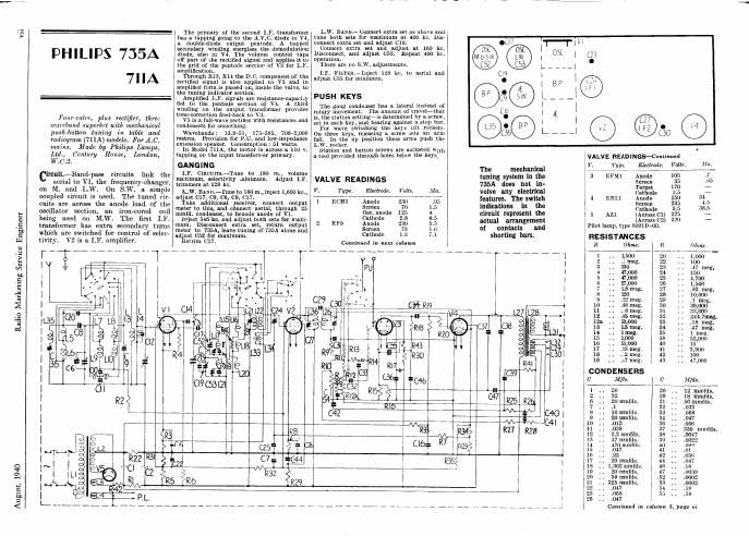
ircuit.~Bnnd-pass circuits link the
aerial to V1, the frequency-changer.
an M. and L.W. 0n S.W. a. simple
coupled circuit is used. The tuned cir-
cuits are across the anode load of the
oscillator section, an iron-cored coil
being used on M.W. The first I.F.
transformer has extra secondary turns
which are switched for control of selec-
tivity. V2 is 3. LF. amplifier.

The primary or the second I r. transformer
has a topping going to the A.V. . diode in V4,
a double-diode output peritode. A tapped
secondnry winding energises the demodulation
diode, also in V4. The volume Control taps
at? part of the rectified signal and applies it to
the grid of the pentode section of V3 for L.l<.
amplification.

Through 1113, R14 the DC. component of the
rectified signal is also applied to V3 and in
amplified form is psssed (in, inside the valve, to
the tuning indicator section.

Amplified L.F. signals ere resistance-capacity
fed to the pentodc section of V-i. A third
Winding on the output transformer provrdes
tone-correction feed-hack to V3.

V5 is n full-WAVE rectifier With resistances and
condensers for smoothing.

Wavehauds : 13.8751, 1757585, 7084.000
metres. Provision for EU. and low-impedance
extension speaker. Consumption: 51 watts.

In Model 711A, the motor is across a 110 V.
lapping on the input transforirer yrimnry.

GANGING

I F. Outcome-Tune to 180 m.. volume
mtimnm, selectivity .ninimum. Adjust LF.
trimmers! at 128 kc.

L.W. Burn-rune to 180 m., inject 1,600 kc.,
adjust 017, co, cs, 09, 017.

Take additional waiver, connect output
meter to this, and meet aerial, through 25
mmfd. condenser, to hexnde anode of V1.

Inject 546 kc. and adjust both sets for maxi-
mum. Disconnect extra net, return outnut
meter to 735A, iecve tuning of 735A alone and
adjust 052 for maximum.

Betrim (717.

'/

L.W. Bun- Connect extra set as above and
tune both sets for Inuilnum at 400 kc. Dis-
connect extra set and adjust 019.

Connect extra set and adjust at 160 kc.
Disconnect, Ind. adjust (:53. nepsst 400 kc.
operation.

There are no s.\V. ndjustnienrs,

1.]3'. FlLTER.r- Inject 128 kc. to aerial and
adjust C35 for minimum.

PUSH KEYS

The gang condenser has a lateral instead or
rotary movement. rise amount of traveiithnt
is, the station settingiis determined by a screw,
set in each key, and bearing against a stop bur.

For wave switching the keys Kilt rockers.
On three keys, 101915ng a screw AELS an arm
[31]. In the up position these arms push the
L.W. rocker. ,

station and button screws are auiustsd wm,
a tool provided through holes below the keys'

VALVE READINGS

V. Type. Elwtmde. Volts. Ala.
1 LCH3 Anode 230 .95
Screen 70 1.5
Use. anode 125 4
Cathode 2.8 6.5
2 EF9 Anode 230 5. 5
Screen 73 1 .6
Cathode 1.3 7,1

Continued in next column

C
@.

C
e

r r.
.0. O
5. Co
l-_V|_'
1 w
e

0LI7 'l-f-T iv

The mechanical
timing system in the
735A does not in-
volve any electrical
leatures. The switch
indications in the
circuit represent the
actual arrangement
of contacts and
shorting bars.

Ir-wanufll"""fffi "Thnu?

EFMi.

EBLI

AZl

caumwowww! m

CONDENSERS

Mfdr.

J7 mmfds.
470 mmfds.
047

22

20 mmfds.

. 1,362 mmfds.

20 mmfds.
39 mmfds.

I 325 mmfils.
047

:068
.047

VALVE READINGS-Continued

Type. Electrodz. Volts.
Anode
Screen
Target
Cathode
Anode
Screen
Cathode
(Across Cl)
(Across cz)
Pilot lamp, type 8091D410.

RESISTANCES
Ohms.

56 mmfds.
.033

.068
.047

.056
330 mmfd 3.
0047

Continua! in column 5. pug: vi

Page 2

August, 1940

Radio Marketing Sewicc Engineer

FERGUSON C
909, 908

MAINS MINORS

to V1, the frequencyvchanger. Trans-
former Coils are also used in the oscillator
section, the anode coils being tuned.
51h; S.W. grid coil remains in circuit on

Trimmer-tuned LF. transformers lead to
V2, the IF. amplifier, and V3, the diodediode
triode. The demodulation and A.V.C. circuits
In straightforward, A.V.C., being applied to V1
and V2 on both bands. V1. V2 and V3 have a
common cathode return.

V3 is resistance-capacity coupled to V4, the
output pentode. v5 is a helpweve rectifier with
a series smoothing choke. All the valves are
run In series and with a line card resistance to
break down the mains voltage.

GANGING .

LF. Cinemas-Tune :0 MW. maximum. 3
Inject 470 kc. and adjust LF. trimmers.

M.W. BAND,-~Tune lo 214 my, inject 1,400 kc. l
and adjust T3, T4. Pad with T5 at 500 111.1
(600 km), rocking gang slightly.

S.W. Ensualrim with T1 and T2 lit com
venlent point at bottom of band. Padding is
fixed.

L.W. BAND (Model MEL-«Adjust 030. and
aerial trimmers an 1,250 in. (240 kc.) and pad
with series oscillator capacity at 2,000 in.
(150 kci).

TSl ¢T4

T2<>
GD

0
® 0'on T' osc <>

Four-valve, plus rectifier, 14.0.7 E LS
D.0. superhet compact covering MODEL 908.~Thir is identical to the 909 RESISTANC S
Show and mediuwmw bands. exceptMiar Elli varilbiy tuned circuits. which 12 Ohms. IL ,
. v r .In .Wave .
110461903 mm medium and 107141 WT? aerial is couneitea through a condenser 1 25,000 11 VOLEr WC TUN E
bands. M ads by Ferguson Radio, to a (Emil which acts as i $3??ng undue 3 :§ ONOF
' ums OI'IDBI )rlmary on . . fl . .30 8X 3. 1
1111;32de Cambridge Road, Enficld, coupiélrug {twirling sliunwt conaansell' is tswitched g i: Chassis layout of the
1 'n. n ..,te .. 'co'ucsasnn
. :ierial coupling mil and isgrclondellzxer red from s 16 M31113 Minor. M05915 CONDENSERS
mum-(Model 909.) The aerial is Iafigrgiifigggre-cmms m mm gm With a g g 909, $0? arfhsimiirair [y . Ill/d. C Mid.
coupled by transformer coils both 1 'irfd I, d ' f D excel) 01' 9 V8 ' A , if 77,7,
primaries and secondaries being switched, :fimrxgdeooupl 113 w. a y con mm mm 10 fl ably tuned circuits. 1x 1' .1100 mmde' :3 I: .353025
' .. .1 23 ,. 2
S ., 100mm. 24 .. .0001
9 .. momma. 25 .. .0005
PL 12 ., .ms 20 .. .02
Hf/lffks 13 .. .000 27 .. .005
' l3 " 'i 3i ' 12
RIB is I: Irmzs . 50 II .02
R5 _ - _ Jffi _ .. _ _ VALVE READINGS
I g l' Type Electrode Volts m.
l ' RIO 'v 1 ECH3 Anode 175 1.5
.T l KI Screen 35 2.5
' R6 | § EFQ gecdnlnode 3.5 4
-_ no e 1 5 5
I C20 1 Screen 35 1.5
1: :2 E303 A or] 90 -
: 7:va : RI .1 7m i301: 150 an
_ . ¥ - - - ~ - V4 r ms germane? $23 5
a 8 0 e -
Cl V2 fl: C2 V5 Pilot lamps, 678, ,2 amp.
- I 2:
SW T2 . -
MW é ; PHILIPS MODEL 735A
_1 Rib
Continuzd [ram page vii
SW 'MW 08:: _L 7 wmumes
2° "(:25 _ C2 L C30 9* Ohm.
a- -. n
7 Ob , 'l- -- 5 "l the .5
T4 R9 R14 RIS C28 C29 4 :2 122.03" 5
5 .. 20
(s . so
csT 7T CI2=|. ; ; 1;:
, 0 .. is
i R4 073 520 l; .: :2"
-=- 0
' W l; 2: f
The circuit of the 999, covering medium and short wavebands. Model 908 covers medium and long bands, but, except ior 1; - - fig: 333 2
the aerial and oscillator oirouits, is the same as the 909. it; .. {1;
is I: 2