Philips 5 dtc module mp 3 service manual

This is the 16 pages manual for philips 5 dtc module mp 3 service manual.
Read or download the pdf for free. If you want to contribute, please upload pdfs to audioservicemanuals.wetransfer.com.

Page: 1 / 16
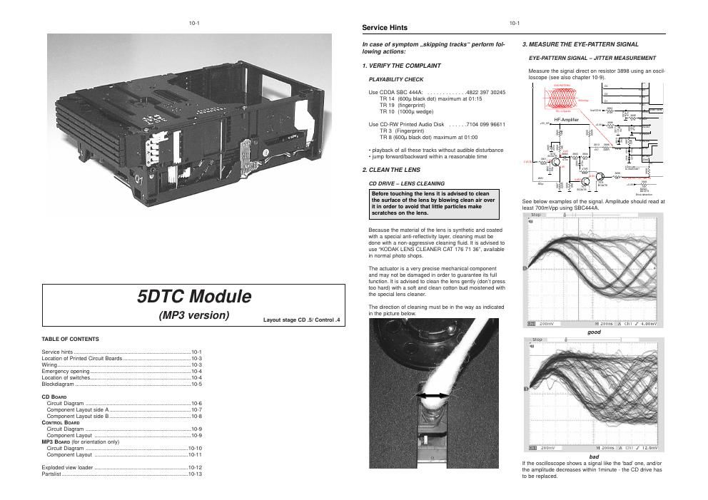
philips 5 dtc module mp 3 service manual

Extracted text from philips 5 dtc module mp 3 service manual (Ocr-read)


Page 1

10-1

5DTC Module

(MP3 version)

Layout stage CD .5/ Control .4

TABLE OF CONTENTS

Service hints .................................
Location of Printed Circuit Boards
Wiring ............................................
Emergency opening.
Location of switches.
Blockdiagram .........


CD BOARD
Circuit Diagram ...............
Component Layout side A
Component Layout side B
CONTROL BOARD

Circuit Diagram ....................................................................... 10-9

Component Layout ................................................................. 10-9
MP3 BOARD (for orientation only)

Circuit Diagram ..................................................................... 10-10

Component Layout ............................................................... 10-11
Exploded view loader ....10-12
Partslist. ....10-13

Service Hints

10-1

In case of symptom ,,skipping tracks perform fol-
lowing actions:

1. VERIFY THE COMPLAINT

PLA YABILI TY CHECK

Use CDDA SBC 444A: ............. 4822 397 30245
TR 14 (600p black dot) maximum at 01:15
TR 19 (fingerprint)
TR 10 (1000p wedge)

Use CD-RW Printed Audio Disk ...... 7104 099 96611
TR 3 (Fingerprint)
TR 8 (600p black dot) maximum at 01:00

- playback of all these tracks without audible disturbance
- jump forward/backward within a reasonable time

2. CLEAN THE LENS

CD DRIVE - LENS CLEANING

Before touching the lens it is advised to clean
the surface of the lens by blowing clean air over
it in order to avoid that little particles make
scratches on the lens.

Because the material of the lens is synthetic and coated
with a special anti-reflectivity layer, cleaning must be
done with a non-aggressive cleaning fluid. It is advised to
use KODAK LENS CLEANER CAT 176 71 36", available
in normal photo shops.

The actuator is a very precise mechanical component
and may not be damaged in order to guarantee its full
function. It is advised to clean the lens gently (dont press
too hard) with a soft and clean cotton bud moistened with
the special lens cleaner.

The direction of cleaning must be in the way as indicated
in the picture below.

3. MEASURE THE E YE-PA'ITEFIN SIGNAL
E YE-PATTERN SIGNAL - JI'I'I'EFI MEASUREMENT
Measure the signal direct on resistor 3898 using an oscil-

loscope (see also chapter 10-9).

EYE warm

W we; can
lair

vum
W
W
W

urns;

um detection

See below examples of the signal. Amplitude should read at
least 700mVpp using SBC444A.

stop firm 4i i7
:1 1

m zdbi'nvm ' m

'ivi Snails 'A'cii'{ i "if" 3. 66W
good
Stop a
,

zde'nv "M'zoons A rm I mom

bad
it the oscilloscope shows a signal like the bad' one, and/or
the amplitude decreases within 1minute - the CD drive has
to be replaced.

Page 2

. . 10-2
SerVIce Hints

4. MEASURE THE LASER CURRENT
CD DRIVE - LASER CURRENT MEASUREMENT

The laser current can be measured as a voltage drop on
resistor 3820. Typical value 170 - 190mV for CD-DA res»
pectively 200 - 220mV for CD-RW.

Laser power control

(example for DAZX drive) U >250mv
stwm l
+5V7HF I 7 5]
E 5 4H7

3817
47R
38t8

3.3V
7879
50307-40

LASER DlODE 2;),

Eli

5. MEASURE THE OFFSETS OF THE CD-DRIVE
CD DRIVE - OFFSET MEASUREMENT

Each photodiode of the CD-drive may have an offset.
This offset has to be compensated by the signal proces-
sor. A high offset of the CD-drive leads to poor playability
of some CDs (skipping tracks).

Start the Service Test Program - section ,,Focus Test
without a CD. Focus sensitivity = CD-RW.

Use a DC Millivoltmeter for measurement. The offsets
can be measured direct on the connector. See drawing
below.

The values from diode A-D should read
0:10mV. Diodes E and F are less critical.

' Sanyo DA12T3|
'1800

16

=IVrefCD1O

EZ'ZH-___ _

mm late

/

(/

./
\

If one of the offsets is higher than itomV the CD drive
has to be replaced.

10-2

WARNING

CHARGED CAPACITORS ON THE SERVO BOARD MAY DAMAGE THE CD DRIVE ELECTRONICS WHEN
CONNECTING A NEW CDM MECHANISM. THAT'S WHY, BESIDES THE SAFETY MEASURES LIKE

- SWITCH OFF POWER SUPPLY

- ESD PROTECTION

ADDITIONAL ACTIONS MUST BE TAKEN BY THE REPAIR TECHNICIAN.

The CD drive forms a compact building block with the CD Board.

The following steps have to be done when replacing the CD mechanism:

9°.\9$9".4>F°!3.!°r

Desolder disc and slide motor

Loosen 2x screw

Disconnect flexfoil from old CD drive

Put a paperclip over contacts of flexfoil to short-circuit the contacts (fig.1)
Remove old CD drive

Mount new CD drive to CD board

Solder disc and slide motor after fixing the drive to the board

Move slide outside

Remove paperclip from flexfoil

Connect flexfoil to new CD drive

Remove ESD-protection (solder joint) from laserunit (see picture below)

Attention: The laser diode of this CD drive is protected against ESD by a solder joint which shortcircuits the

laserdiode to ground.
For proper functionality of the CD drive this solder joint must be removed after connection the drive to
the set.

Flex Foil
8001