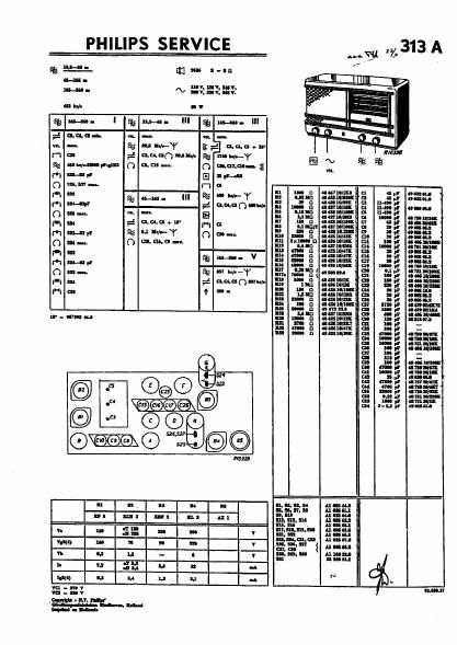
Philips 313 a service manual
This is the 9 pages manual for philips 313 a service manual.
Read or download the pdf for free. If you want to contribute, please upload pdfs to audioservicemanuals.wetransfer.com.
Extracted text from philips 313 a service manual (Ocr-read)
Page 1
PHILIPS SERVICE
g vi; as us :-In
a.
M. ~ 22:23::
Hi I.
fins-un- I fins-a. III igm-m-"I
,-_£ nun-h. w. In v... -.
"L- gaunt-Y 3:7: ammun-
H a: ,-_ mucous-v- % Hunky
% «Bump-an O (am-u. O munch-1|
m n.3,! 3 8.1.4:
0 mm... n I!
u up n uuumu u «I amuu
m I8 % m- III 5%? Ho-Y = Iglg :2? g «E: "mu
mg... -_£ gaunt-halt u nun-On «mun-l u u-mpr out
n m _,_ :5 mm «annu- u 4,:
0 n . B :: 3-3 mm... 3 a" :2...
M "- M F = swam"... g =5 "m
r" "H * "4 0 m ::.- rm, mm a: a =3
O as 0 cu-3'- m ,(m tum-m cu mus «mm-n."-
Mm mamnuumas autumn
Q M_ V In mun manual as up! nuts:
m an. n um: :11 'pl nun
min-up mmfiaamgmflzgm
O m- * "Y :z- Mf... 22 g $5 awn-'5
{1 as # DWASOVW' u! I: u % a) n5 nan.
-- I. I. (I aim D. .p "mil-l
("I a: I u: um «mums as an! «0-1.:
m an. 1: animal 1: an umu
m 1- u «and/Ia: a: run! mug-Ht
: "v.2 3:... g ":5 ma":
Ir-mmm .- n a! I, IS], .mfl
III 3mg «am at u"! ._
a 23 32W. 3 I: .am
«:4 nu: nun-n:
m I! um
as my a -
a nu! ..
3 $5 "1",...
on my amm-
w mu.- «mm--
as an menu
a: mun! «mm
on ma; «mum
at my «mm
a 1...: 23mm
'3. SXHIT «mm
=
Anna.-
Alum
HOS
Inc-nu
mum
n-m
nus;
nun;
unuu
Anna:
mum
l"
Page 2
STRICTLY CONFIDENTIAL
FOR PHILIPS SERVICE DEALERS ONLY
0
connam "39
PHILIPS
SERVICE DOCUMENTATION
for receiver
313 A
FOR A.C. MAINS FEEDING.
VAVERANGB
Shortwave l : 135-45m( ZZZ- 5.57m)
Short wave 1. 45 -l65 m 6.67- I! Inc)
Medium wave :165 -560 m 1000 -535.6 Kc).
CONTROL KNOBS
l-Iomrritht to left:
2. 633.... m...
Retrimmin; Is wry:
a. When a coil or condenser III me I. F. HF. ot oscillator
t has been renewed.
h. en the neeiver is not aeImitI've or aeleetive enwgh.
It it not necemxy to the receiver nut 05' In mbinrt; all
trimmen banana ammihle after remmal of III: rear panel
and the base plate. The positions of the trimmer: are indi<
and in fi. 4 Ind 5. AI regards the necesury trimming
welt ride lint of par: and tools.
On all v-vdtandi the dII-tillamr frequency '3 higher than the
Billing free. them. circuiu.
r... IF. I. 331.."
'l'heLF bandwidth 1 z 10 Ii 11.5 b:
mhandvidxallmkclz Ioillflltc.
A. LP. CIRCUITS.
1. Earth the Iet and twitch to medium wave hand
Turn the variable modem" to minimum _potition.
2. (bum Ihe output indicator via a trimming tIaI-u-
former to the Intention loudspeaker Inches. Shut:-
eireuit CS}
3. Appl¥ a modulated IipIal of 452 he via a conden-
WHOM («all In HI: first grid of ll.
4 the third dreuit by scouted-5 a condenser
of m mil: In parallel Irith 52$.
5 Tune 516-527 to nuaimum autpur, then remove do
6. amine mdeutsdfrqmfisziy "d
Den-II: in» wet muecu'ng-oo cuter
oflnnulinparallelwith SZUI
7 Tune $15 In maximum output.
I Remove the damning condenser from 524 and
dawn: the first menu by connecting a condenser
of IO IAF' n. parallel with $23.
9. Tune $24 to maximum III.
IO. mauve the detaining con er and demne the
monddrtuirhycmectingaeondnnufwfipli
In parallel anti-I 524.
Tune $23 In maximum output. Remme deumin;
condenser and real the com.
HF. AND OSCILLATOR CIRCUITS.
SHORT WAVE I (I). 5-45 m).
1 heel: the Iet and twitch to than wave 1.
2. Gm'rlteuutptttindiumtothenmherrin-
3. A y to die aerial via the than wave
:Piglmyae rial. 1 mm dual of 20.5 me.
.4. Armin turIe thereuiver In thu frequency by
mean: the variable oondenier (first mammum
tuning frnm minimum tawdry).
rw
I.
4.
Width: 50 cm I
I:29 an
Heidi
be...» 2.5 an
Volume contrul with mains twitch.
Tone control.
DIMENSIONS.
knobs included.
WEIGHT: Iu.7s kg, tulle: included.
We THE RECEIVER.
ll.
5.
Eunecfs. (215 to maximum output. Seal trimmer
'15
NOTE C24ittunflltoafixedt: militia
not be altered. Wk, y
SHORT WAVE 2 (45465 In)
I.
1.
J.
4.
fit the 15° gauge (lo-at capacity).
Swath the set to short wave 2.
Apply a mndillated signal of 6.! III: via the short
wave dummy aerial to the raid socks.
Accurately tune the set In din frequency viIII the
aid of C25. C16 and C9.
Sal the trimmen.
III. MEDIUM WAVES (165-560 my
C.
I.
2.
3.
I.
9.
In
11.
Fit the 15° pug: (Invert capacity).
Switch the set to medium uava.
ApEly a modulated signal of mo he to the aerial
:1: via IlIemnnzl durum aerial.
Aotunuely Inn: in set to is frequency with Ihe
aid of C26. C17 and cm.
Canneet GM 240 to the anode of LL and the
avian: indIeatoI m the GM 1404. Short-«mi: the
later
Appl magi-5e) Trial socket of the set to he rimmed
VI: 2 mal dummy aerial, a modulated signal
of 600 Ire
Aeeuraeely lune Ih: set to thin frequency with the
tuning knob.
Tak e away GM 240. mnneet the «Input indicator
It; the set In he muted. Remove the ahofldrcult
a C5.
DO NOT TURN THE VARIABLE CONDENSER.
Tune C10 tn Intximum 0!!le
Turn the variable condemn against du 15" page
(lowestiap :7).
A ypl mtheacrialsotltetohhemwbeuimmed,
III: e normal d aerial, a signal of [740 he
Tune C16. C17 and 10 to maximum WI. 5.1]
C10. C17. C16 and C30.
ADJUSTING THE DIAL
2.
Switch the receiver to the medium wave hand.
Connect, the output oscillator.
thetuialmrketriaannmmldltm
Quill a modulated dual of [57 kc. $35!) In).
Aanirawl mine the receiver to this requclcy.
Sli;htly the screw an it pointer far am,
dung the string and more the painter until It. points
extetly (03 In.
firm the men.