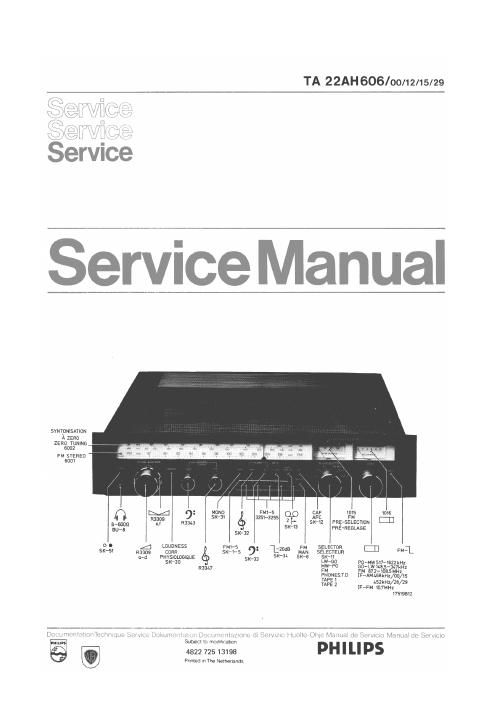
Philips 22 ah 606 service manual
This is the 12 pages manual for philips 22 ah 606 service manual.
Read or download the pdf for free. If you want to contribute, please upload pdfs to audioservicemanuals.wetransfer.com.
Extracted text from philips 22 ah 606 service manual (Ocr-read)
Page 2
Alignement 0 g Q :1
Rielacc SK... C) -" 2051 ril-j Y 7
2052 3051
452 kHz 5111
AM-IF MW 468 kHz Min' cap' 5121 @ Max + symm
AM-Fl 470 kHz 5120 = . .
(=10 5115) ( fo 5115)
(+1 kHz)
f0 5115 3 5111
5120 Q>
5121 Min. + symm.
AM-OSC LW 147 kHz ® Max cap 5123 ® or ®
(+1 kHz) max
MW 512 kHz
(+ 1 kHz) 5122
1635 kHz _
(+1 kHz) Min. cap 2197
AM-RF MW 600 kHz ® @ 5118 ® or
1+ 1 kHz) Max <>
LW 155 kHz
1+ 1 kHz) 5119
MW 1500 kHz
1+ 1 kHz) 2186
Min. cap. 5107 5112 <9 + <9
FM"F FM 5109
i 10.7 MHz 5113 Max. + symm.
A1 250 kHz
50 H" 5107
i107MHz 5113 <6) ®
13 I ©+ ®
< 20 mV 7
CS 65 814
Before proceeding to trimming, short-circuit
point 14 of IC 6111 by connecting it to the mass.
Switch off the AFC (automatic frequency control).
Interrupt solder bridge .
Adjust the RF. generator In such a wav that
a symmetrical response curve is obtained on
the screen (= f0 5110).
The input signal shall be as low as possible.
Adjust for max1mum linearity of the Scurve.
Close solder bridge
Adjust for zero-axis crossing (red LED shall
burn glaringly).
Mark at scale.
Meter deflection 2 8 divisions.
Eliminate short-circuit at point 14 of IC 6111.
Adjustment output amplifier
Direct current adjustment - Left (Right).
With theaid of R3527 (3523) adjust the quiescent
current through the output transistors to 50 mA 1 5 %.
To be measured with a non-earthed mV~n1eter connected
across the resistors 3505, 3507 (3506, 3508).
The deflection shall then be 24 mV i 5 %.
Inspection DC protection
- Connect a resistor of 270 k9 between the negative
pole of C2411 and point +1 of the power supply.
The relay shall then be released.
- Connect a resistor of 220 k9 between the negative
pole of C2414 and point -1 of the power supply.
The relay shall then be released.