Philips 22 ah 578 service manual

This is the 22 pages manual for philips 22 ah 578 service manual.
Read or download the pdf for free. If you want to contribute, please upload pdfs to audioservicemanuals.wetransfer.com.

Page: 1 / 22
philips 22 ah 578 service manual

Extracted text from philips 22 ah 578 service manual (Ocr-read)


Page 1

A 22AH578/00/16

Serwgoe
gewgoe
Servrce

Part 1

1 5862A

Circuit Description

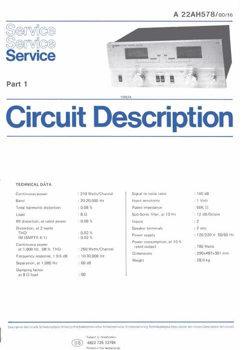
TECHNICAL DATA
Continuous power : 210 Watts/Channel Signal to noise ratio : 100 dB
Band : 20-20,000 Hz Input sensitivity : 1 Volt
Total harmonic distortion : 0.08 °/o Rated impedance : 50K 9
Load : 8 $2 Sub-Sonic filter, at 10 Hz : 12 dB/Octave
IM distortion, at rated power : 0.08 /0 Inputs : 2
Distortion, at 2 watts Speaker terminals : 2 sets
lrMH?SMPTE 4: 33;: Power supply 2 120/220 V 50/60 Hz
Continuous power Power consumption, at 10 %
at 1,000 Hz, .08 % THD : 250 Watts/Channel me" mm" 1 780 was
Frequency response, t 0.5 dB 1 10-30,000 Hz Dimensions 2 ZOOX457X381 mm
Separation, at 1,000 Hz : 60 dB Weight 2 28.6 kg
Damping factor
at 8 (2 load : 90

Description des cicults Schallungsbescnrezbung Kredslobsbesknvelse Kretsbesknvelse Krelsbesknvmng Toimmtaselostus Descnzione del cwrcuno DESCHDUOD del CerUllo

SLDECI to modification

4822 725 12784

Printed mThe Netherlands

Page 2

zmw t
VJ},
775v m A
ms n
47
030ng n
232N2l/2W L
i Wl m B
I 3 -_ V '.
535$ islfn' 6 ::::W n
l_ 7531 I 7 Fume W :ggpleggén:
. l 32%: /P1 zgazlazLQ 0315 Ass
:2_ 23 L/ a ' 0307 232mg:-
.7. 0305 t 232N2
i ,1 232N2 . y W $53
at 0 7 i_.44",_,72 7, 7*,

receives
ffers DC
( source is

nd R152.
i2

applied
lit (pin 2).
Tier (pin 1,
ons. This
Enditions.


PART ali-FRONT an.

11

ms: ASS'Y 70337| |

m was as non |
eels . TEE iii w 05v
\ m - rim-F m
i am.» 4mm 9 L >

0° \Q um um \ 75 D. z
l I iosA\.i 0v iv a: IC106A\ 0" ICIO7A
, 3 SIleal . my

3 6l2l )- i
who:

22x

mu

3:
355M

3 an}.
em my;
22 mg

Zr-r. :


5 PART 6F- PROTECTION VL
l-rm 5 an. ASS'Y 703373
L 7 1 a
P/ulfi? A

nsoz
so

0302
. 232N2

3-
355N|

70 am €303 l

1

embed PART or
FRONT BD,
ASS'Y_ 10387]


m
was
41 x

m5!

..
cf;

PART OF

l
l \nliie m-z .
02 IzzllDlCIOSB :e\ 0») M w licro7e\ $1263 -
I ma: am. my \ a
' , ,9v 4 5:1 //75"szims1i l/[4/ l -
[we 2% .
«x mm

FRONT ED.

The gain of |C106 is controlled by the feedback from a
network consisting of R151, R152 and R149, which is
applied to the inverting input (pin 2)

The output of lC106 (pin 1) is half-wave rectified by
D111 and applied to the sample and hold circuit com-
prised of C121, R154 and 0111. The sample and hold
circuit is used to increase the duration of the DC level
applied to the input of 10107 (pin 3). This action damps
the level meter indication for more accurate readings. The
design of the circuit allows C121 to charge quickly and
discharge slowly. C121 constantly charges and discharges

7.5V ASS'Y ToseZL -.¥

lleUFll

with reference to the audio signal.

The voltage developed by C121 is applied to the input of
|C107 (pin 3). |C107 functions as a voltage follower and
offers a high input impedance for minimum loading of the
input signal, while its low output impedance is required
to drive the level meter. The signal at the output of 10107
(pin 1) is coupled directly to the inverting input (pin 2).
This feedback insures 1C107 operates with a gain of unity.
Simultaneously, the output of IC1D7 (pin 1) is applied
through R155 to the positive terminal of the level meter,
which indicates the instantaneous peak power applied to
the speaker.

0362 292