Philips 22 ah 578 int service manual

This is the 22 pages manual for philips 22 ah 578 int service manual.
Read or download the pdf for free. If you want to contribute, please upload pdfs to audioservicemanuals.wetransfer.com.

Page: 1 / 22
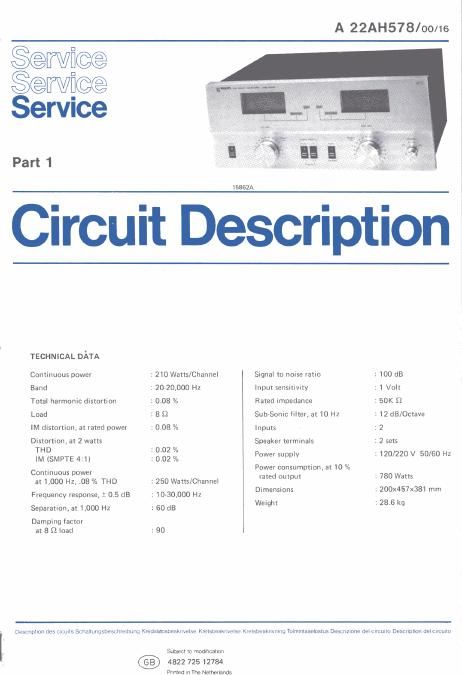
philips 22 ah 578 int service manual

Extracted text from philips 22 ah 578 int service manual (Ocr-read)


Page 2

OZIZ 02l4 , 0216 ov
6 6 1

L7; .-_

QZIE QZIS

@QJQ

ed through
it receives

,offers DC
I source is
and R152,
be applied
.11 (pin 2)
fier (pin 1,

\OZIS
1

,l 1

sales
47x mos me)

11

PART (Ya-WONT BD
ASSY 70387|

osv

a
ma
22v

tiw

' 125
125) GM; wax-H m.
we mm mm
v r \ 220m:

04v lelOTA\\ i J

11155

l \ 10v \ 3500 .
l S'SSL \ V 1 3212015; / 155v 3 6121131 \ L
s 1/// 2423}. L/ :22 35a: / _
3' 7 10,:
355m W .
range |
A4
i 7 7 i ZJPIJlai V yA
> 7- _ '1
~L PART ofpnomcnou _- 1,1,
HQ- BD, ASSY 703873 rig;- A, o-A-
egg , o , «(7"
LL "iv V") fl ' I " ,3 miez
can 3 m2 \ 1m 1:52 t
W L W D 4.1.: w
10302 in re 14w ____
i 0302 fl 4 1 w t: 0312 W 5
, 232N2 a K302 w N2 ,5» ,i
i 1% 10310573,, '
l 83P| 10x *ev I
355m , oslns

0306
ZBZNZ )

mm
mm

0
0301M; , l w

180K

i
av

at 07 We)
180K lav

R303
150x

07 $3044

7511) "747 f 73v saw.
' a w 9308
_ 10 F, . Q 232N2 203323:
36 Q YYENM
Allis; {561' 33,0 9,;ng
m use may 29532, m

1 «ONMS CSMOFE 95°
7; N2 22 5
9 5mm ,
w 1
mi: iasfw

1o 3v

vent

eusoa PART OF
FRONT BD.
ASS'Y 70387! i

was PART OF
FRONT BD

mm:


was

*. fl
m

22M LL

02l7

PART OF FRONT BD.
5" ASS'Y 70387l_

osis , ASSY_ 703371
:53?qu /L A 232? 03|5
/ 7 i 0307 232N2
0305 T , 232112
232112 J o, lav
, , 7 j ,,,7
m <15»

The gain of IC106 is controlled by the feedback from a
network consisting of R151, R152 and R149, which is
applied to the inverting input (pin 2).

The output of lC106 (pin 1) is half-wave rectified by
D111 and applied to the sample and hold" circuit com-
prised of C121, R154 and D111. The sample and hold
circuit is used to increase the duration of the DC level
applied to the input of |C107 (pin 3). This action damps
the level meter indication for more accurate readings, The
design of the circuit allows C121 to charge quickly and
discharge slowly. C121 constantly charges and discharges

mum

with reference to the aUdio signal.

The voltage developed by C121 is applied to the input of
|C107 (pin 3). lC107 functions as a voltage follower and
offers a high input impedance for minimum loading of the
input signal, while its low output impedance is required
to drive the level meter, The signal at the output of 10107
(pin 1) is coupled directly to the inverting input (pin 2).
This feedback insures |C107 operates with a gain of unity.
Simultaneously, the output of |C107 (pin 1) is applied
through R155 to the positive terminal of the level meter,
which indicates the instantaneous peak power applied to
the speaker.
CS 62 292