Philips 209 u service manual 2

This is the 3 pages manual for philips 209 u service manual 2.
Read or download the pdf for free. If you want to contribute, please upload pdfs to audioservicemanuals.wetransfer.com.

Page: 1 / 3
philips 209 u service manual 2

Extracted text from philips 209 u service manual 2 (Ocr-read)


Page 1

PHILIPS Model 2090

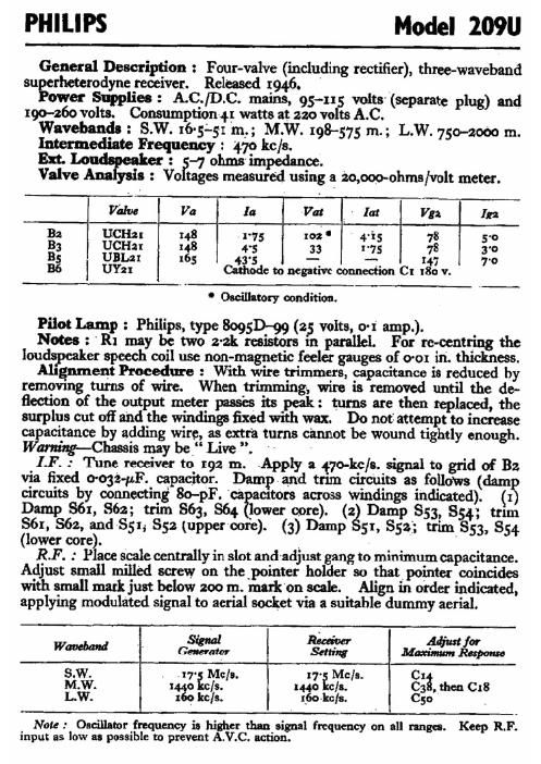
General Description : Four-valve (including rectifier), three-wavcband
sugerheterodyne receiver. Released 194.6. ' .
ower Supplies : A.C./D.C. mains, 95-115 volts (Separate plug) and
190-260 volts. Consumption-4t watts at 220 volts A.C.
Wavebands : S.W. 16-5'.51 m,; M.W. 198-575 m.; L.W. 750-2000 :11.
Intermediate Freq ency : 47o kc/s.

Ext. Lo : -7 ohms impedance.
Valve 8 : Vo tages measured using a '20,ooo-ohms/volt meter.
Valve Va Ia Vat . . Ia! I m I In
Ba 11ch 14.8 .1-75 ma ' 4-i5 78 5-0
33 UCHar 148 4~5 33 1-75 78 3'0
35 URL 165 43.5 - ~- 147 7~o
86 Usz Cathode to negative connection Cr :80 v.

' Oscillator-y condition.

PilotLam : Phili s, e 8095D-99 (2 volts, o-x amp.).

Notes : R}: my bf: twt?z'2k resistors 1"; parallel. For rc-centring the
loudspeaker speech coil use non-magnetic feeler gauges of 0-01 in'. thickness.

Alignment Procedure : With wire trimmers, capacitance is reduced by
removing turns of wire. When trimming, wire is removed until the de-
flection of the output meter passe its peak: turns are then replaced, the
surplus cut off and the windings fixed with wax. Do not attempt to increase
capacitance by adding wire, as extra turns cannot be wound tightly enough.
Wanting-Chassis may be Live . '- '

LF. : Tune receiver to I92 m. Apply a f7o-kc/s. signal to grid of B2
via fixed 0-032-pF. capacitor. Dampand trim circuits as folloWs (dam
circuits by connecting 8o-pF. ca amtors across windings indicated). (3
Damp 861, 862; trim 863, 864 lower core). (2% Damp $53, 854; trun
861, S62, and $51; 852 (upper-core). (3) Damp 51, $53; trim SS3, 854
(lower core). \ . '

RF. . Place scale centrally in slot and-adjust gang to minimum capacitance.
Adjust small milled screw on thepointer holder so thatpointer coincides
with small mark just below 200 m. mark'on scale. Align in order indicated,
applying modulated signal to aerial socket via a suitable dummy aerial.

. SW Rm. ' AW for
WW ' Generator | Swag um Response
S.W. . .17' Me a. l ' Mela. CI
M.W. 14.40 Ext/3.] 144: isle. C3§Lthen C18
L.W. 169 Ire/s. r_6°~kcls. Cso _

Note .- Oscillator frequency is higher than signal frequency on all ranges. Keep RF.
input as low as possible to prevent A.V.C. action.

Page 2

x2
ONH
Sn
:3
a:
30H
235
290
SH
.50

.hm ooo€u
.hm 80»
ME on
#3 0M3:
on «my... v.3 o .u
ma mm .mm we
own 0n Hm can.
it «mm .mm 80%?
290 3% .mn coo 5+
on" mm .mm «m
03 E .hn one
can mm Hum can~
can NM .hm 80."
can; mm .9. 2K v

6%
a?" 352

«.30
«3.0
n30
Oahu
«80
menu
«30
mono
+30
menu
«05
~20
85

n8

n5
.Wm 3a 3.0
.mm amt 3
Huh «V 0+0
fin an wno
.mm «a 80
.mm on 30
.mm an no
4mm an no
.mm «MW MW
. a
Q a
nu
figs