Philips 202 service manual

This is the 4 pages manual for philips 202 service manual.
Read or download the pdf for free. If you want to contribute, please upload pdfs to audioservicemanuals.wetransfer.com.

Page: 1 / 4
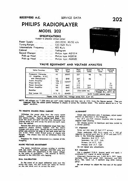
philips 202 service manual

Extracted text from philips 202 service manual (Ocr-read)


Page 1

RECEIVERS A.C.

PHILIPS RADIOPLAYER

MODEL 202 -
SPECIFICATIONS

{Subiect to alIeration without notlcal
ZOO/ZSOV, 40/50 C/S
550-1620 Kc/s

SERVICE DATA

Power Supply
Tuning Ranges

Intermediate Frequency 455 Kc/s

Cabinet ,, .. .. Radiogram

Record Changer ..... Philips type AGlOl4
Pickup Head Philips type AGSOIS

Pick-up Head

Philips type AGSOZS

VALVE EQUIPMENT AND VOLTAGE ANALYSIS

. Wu Valva Plate Screen l Osci P. Cathode
Valve Funclldfl No I 7W! Volta Volts Volts l Volta
Frequmcv Converter . vi GAN'I 237 46 72
LF. Amplifiar, AinC.
and Demodulatar vz 6N3 237 46 I
Audio Amplifier r ya. 55 -'
zax7 r
Phase Splitter ,r var, ' |I5 ai
pom Amplifier v4 6M5 275 237 79
Pmr Amplifier vs 6M5 275 237 1:9
Rectifier 1 vs I 6V4 253/253v N; éfitlfigd 54* 2" DC
Dial lamps I2) v11, I2 l 304% 6.5V, 0.31». tub?
Heater Volts, 6.35V AC; Voltaga across R27, 2.2V DC

NOTE: All voltages are "LOGO ohm: per volt motor wading and may vary : I0% from the "gums canted. Thay ara
M 53m tho socket wins Indicatod to dIassis or across the resistors listld. Tha maiwr should ha in a "no
m" can Iriun.

TO REMOVE CHASSIS FROM CAIINEI

Mthduw the power plug from the mains outlet
aodut. Loosen the four knob retaining grub acruws
and move knobs. Ramon cabin-t back panel. Um
scram the aerial and earth terminal strip, disconnect the
lntarnal Mil wire and unclip the aerial and aarth luds
horn tho cabinet.

Ramm- the pick-up and loudspeaker plugs from their
nmcliva chassis sockets {Wither with tho record
Chang-r unit power plug. Ettract the two wood screws at
althor alde oxtrorna top Ode: of dial hack platl and the
two 5/32" Whit. metal thread screws at chassis sid-
flanoos. Th- daaaaia may now be withdrawn from the

ALIGNMENT

Check dial Olibralinn and, it necessary, adjust cursor
position as daacribed in the foregoing

For LET. and RF. trimmer louticns refer to circuil
diagram lnut drawinqi

Sal vall-IIII Control to fanirrlurn and tone (MINI Y!)
a central position.

I.F. Milan-n0
Screw oul iron eon or 2nd I.F.T. primary.
Apply modulated 455 Kcls signal via a lot) pF

capacitor II: contrvl grid (pin 2) of VI and peak LET,
com in th- following sequence-

cabin-t.
Pmdure (or dust replacement is a ravenal of the 5mm! '2'! IF}: -7)
towing. Secondary st I. . . (LG)

Primary 1st I.FrT (LS)
Primary 1nd I.F.T. lLBl
Do not mpeat any adiustmants.

RJ. Alla-anon

Use a standard R.M.A. dummy alrlal and apply a
modulated R.F. signal to aerial terrninalr

Alignrnant fraquancies are: IAZD Kc/s, 3Xl lpnk
oscillator (can and aerial (C2) trimmers), and 600
Ke/a, 72L lpeak L31 4 oscillator slug while rocking
gang).

Do not attompt to adjuat tha Imm ot th- a-n'al
I.

MAINS VOLTAGE ADJUSTMENT

Th- powar transformer primary winding is pmldea
wIIh two mains voltaga tawlnwlOO/ZJO volts and
140/150 volts-for adiustment to the supply voltage
at the palm of Installation The receiver Is factory
adiust-d to th- 240/250 volt: tapping.

DIAL CALIBRATION

In the event of an equal calibration error over the
onlirie dial stale, [ha dial cursor can easily be moved A
on tn. dial drive cord to correct the enor. an