Panasonic wj mx 10 service manual

This is the 64 pages manual for panasonic wj mx 10 service manual.
Read or download the pdf for free. If you want to contribute, please upload pdfs to audioservicemanuals.wetransfer.com.

Page: 1 / 64
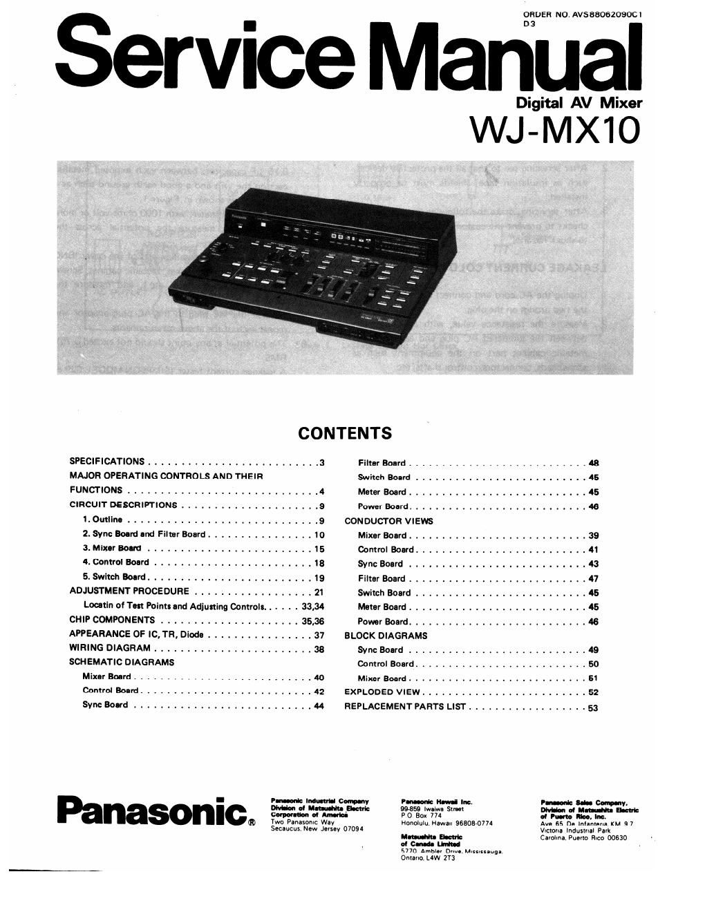
panasonic wj mx 10 service manual

Extracted text from panasonic wj mx 10 service manual (Ocr-read)


Page 1

Service Ma

nual

mguflANIMka

WJ-MX1O

CONTENTS

SPECIFICATIONS .......................... 3
MAJOR OPERATING CONTROLS AND THEIR
FUNCTIONS ............................. 4
CIRCUIT DESCRIPTIONS ..................... 9
1. Omllno ....... . . .9
2. Sync Board and Filter Board ................ 10
3. Mixcr Balm ......................... 15
4. Control Board ........................ 18
5. Swlrch Board ............... . . . . 19
ADJUSTMENT PROCEDURE .................. 21
Loo-tin of Ten Poim: and Adjusting Controlr. . . . . . 33,34
CHIP COMPONENTS ....... 35,36
APPEARANCE OF IC, TR, Diode ................ 37
WIRING DIAGRAM ........................ 38
SCHEMATIC DIAGRAMS
Mixar Board ........................... to
Control Board .......................... 42
Sync Board ........................... 44

Filmr Board ........................... 48
Switch Baird .......................... 45
Meter Board ........................... 45
Power Board ........................... 46
CONDUCTOR VIEWS
Mixer Board ........................... 39
Control Board .......................... 41
Wm: Board ........................... 3
Filter Board . . . . . . . . . . . 47
Switch Board .......................... 45
Meter Board ........................... 45
Power Board ........................... 46
BLOCK DIAGRAMS
Wm: Board ........................... 49
Control Board .......................... 50
MixerBoard.. .. .. .. 51
EXPLODED VIEW ......................... 52
REPLACEMENT PARTS LIST .................. 53

ORDER NO AV588062090C1

Panasonic»

Two Plnasonlc Way
Secaucus New Jersey 07094

PM Hlvlll Into
99-859 lwliwa Srml

PO Box 774

Honolulu Mawan 96303-0774

ram-Inh- Ehml:

or c-naa Lbrlhl

57m Amblar mm Mlssrssauga
Omano, LlW 2Y3

Vucrona Induslnal Park
5mm: Puma Rico 00530

Page 2

SAFETY PRECAUTION

GENERAL GUIDELINE LEAKAGE CURRENT HOT CHECK

When service is required, observe the original lead
dress. Components, wires or cables that indicate
evidence of overheating or other electrical or
mechanical damage should be replaced.

After servicing see to that all the protective devices,
such as insulation tape, shields must be properly
installed

After servicing, make the following leakage current
checks to prevent the customer from being exposed
to shock hazards,

LEAKAGE CURRENT COLD CHECK

Unplug the AC cord and connect a jumper between
the two prongs on the plug.

Measure the resistance value, with an ohmmeter,
between the iumpered AC plug and each exposed
metallic cabinet part on the equipment such as
screwheads, connectors, control shafts, etc.

When the exposed metallic part has a return path to
the chassis, the reading should be between 1M ohms
and 5,2M ohms. When the exposed metal does not
have a return path to the chassis, the reading must
be °°. (infinity)

Any resistance value below this range indicates an
abnormality which requires corrective action.
Repeat the' test with the AC switch In the "OFF"
position.

Plug the AC cord directly into adaptor socket and
plug adaptor into the AC outlet. Do not use an
isolation transformer for this check.

Connect a 1.5K ohms/10 watt resistor, paralleled by
0.15 uF capacitor, between each exposed metallic
part on the unit and a good earth ground such asa
water pipe, as shown in Figure 1.

Use an AC voltmeter, with 1000 ohms/volt or more
sensitivity, to measure the potential across the
resistor,

Check all exposed metallic parts of the cover (BNC
connector, Handle bracket, Metallic cabinet, Screw-
heads. Metallic overlays, etc.), and measure the
voltage at each point.

Reverse the AC plug in the AC plug adaptor and
repeat each of the above measurements.

The potential at any point should not exceed 0,75V
RMS.

A leakage current tester (SIMPSONMODEL 229 or
equivalent) may be used to make the hot checks.
Leakage current must not exceed 0.5 milliampere.
In case a measurement is outside of the limits
specified, there is a p0§ibility of a shock hazard,
and corrective action must be taken before return-
ing the instrument to the customer.