Panasonic wj ave 55 service manual

This is the 40 pages manual for panasonic wj ave 55 service manual.
Read or download the pdf for free. If you want to contribute, please upload pdfs to audioservicemanuals.wetransfer.com.

Page: 1 / 40
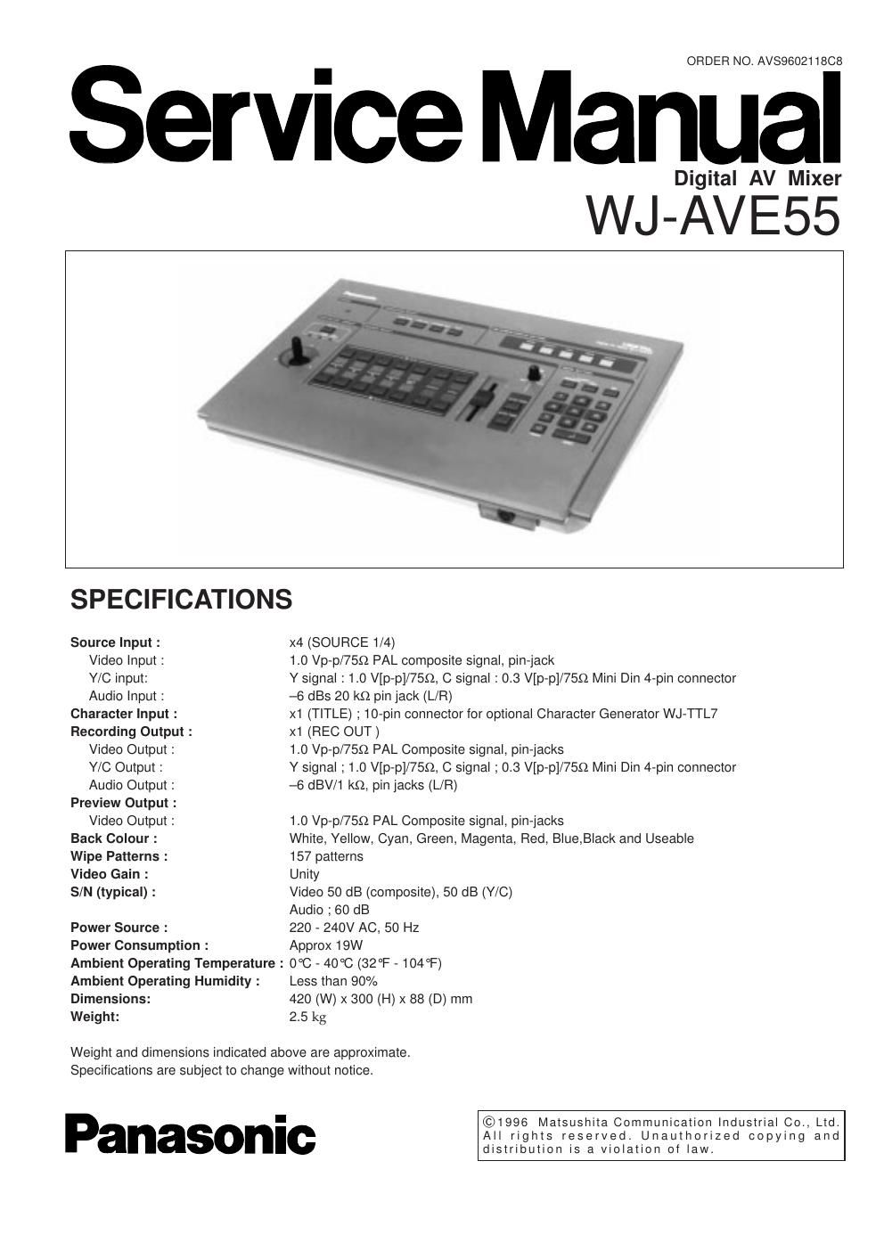
panasonic wj ave 55 service manual

Extracted text from panasonic wj ave 55 service manual (Ocr-read)


Page 1

This service information is designed for experienced repair technicians only and is not designed for use by the general public. It does not contain warnings or cautions to advise non-technical individuals of potential dangers in attempting to service a product. Products powered by electricity should be serviced or repaired only by experienced professional technicians. Any attempt to service or repair the product or products dealt with in this service information by anyone else could result in serious injury or death. ! WARNING CAUTIONRISK OF ELECTRIC SHOCK DO NOT OPEN CAUTION: TO REDUCE THE RISK OF ELECTRIC SHOCK, DO NOT REMOVE COVER (OR BACK). NO USER SERVICEABLE PARTS INSIDE. REFER SERVICING TO QUALIFIED SERVICE PERSONNEL. This symbol warns the user that uninsulated voltage within the unit may have sufficient magnitude to cause electric shock. Therefore, it is dangerous to make any kind of contact with any inside part of this unit. This symbol alerts the user that impotant literature concerning the operation and maintenance of this has been included. Therefore, it should be read carefully in order to avoid any problems. There are special components used in this equipment which are important for safety. These parts are indicated by the Y mark on the schematic diagram and the replacement parts list. It is essential that these critical parts should be replaced with manufacturer's specified parts to prevent shock, fire, or other hazards. Do not modify the original design without permission of manufacture. IMPORTANT SAFETY NOTICE CONTENTS MAJOR OPERATING CONTROLS AND THEIR FUNCTIONS........................................................................................... 1 SYSTEM CONNECTION...................................................................................................................................................... 5 CIRCUIT DESCRIPTION IC DESCRIPTION .............................................................................................................................................................. 6 ADJUSTMENT PROCEDURE..............................................................................................................................................27 LOCATION OF TEST POINTS AND ADJUSTING CONTROLS.........................................................................................30 APPEARANCE OF IC,TRANSISTOR AND DIODE.............................................................................................................31 CHIP COMPONENTS...........................................................................................................................................................32 BLOCK DIAGRAM SWITCH BOARD ...............................................................................................................................................................34 MAIN BOARD(1/2) .............................................................................................................................................................35 MAIN BOARD(2/2) .............................................................................................................................................................36 SCHEMATIC DIAGRAM MAIN BOARD(2/2) .............................................................................................................................................................38 MAIN BOARD(1/2) .............................................................................................................................................................40 SWITCH BOARD ...............................................................................................................................................................41 POWER BOARD ................................................................................................................................................................41 CONDUCTOR VIEW MAIN BOARD ....................................................................................................................................................................37 SWITCH BOARD ...............................................................................................................................................................41 POWER BOARD ................................................................................................................................................................41 EXPLODED VIEW................................................................................................................................................................42 REPLACEMENT PARTS LIST.............................................................................................................................................43 Standard Accessory Optional Accessory Power Cord 1 pc. Character Generator WJ-TTL7

Page 2

1 POWER Section (2) Power Indicator Side View (1) Power Switch (POWER ON/OFF) (3) Wipe / Mix Selection Button (WIPE/MIX) Used to select either the Wipe or Mix Effect. Lighting : shows the Wipe selection Blinking : shows the Mix selection (4) Luminance Key Button Used to replace certain luminance of one picture with a second picture. TRANSITION SELECT Section POWER OFF ON POWER TRANSITION SELECT WIPE/MIX LUM KEY CHROMA KEY SET (5) Chroma Key Button Used to replace certain colour of one picture with a second picture. (6) Set Button Used to select the position for the chroma function. MAJOR OPERATING CONTROLS AND THEIR FUNCTIONS