Panasonic sl ph 660 eg service manual

This is the 43 pages manual for panasonic sl ph 660 eg service manual.
Read or download the pdf for free. If you want to contribute, please upload pdfs to audioservicemanuals.wetransfer.com.

Page: 1 / 43
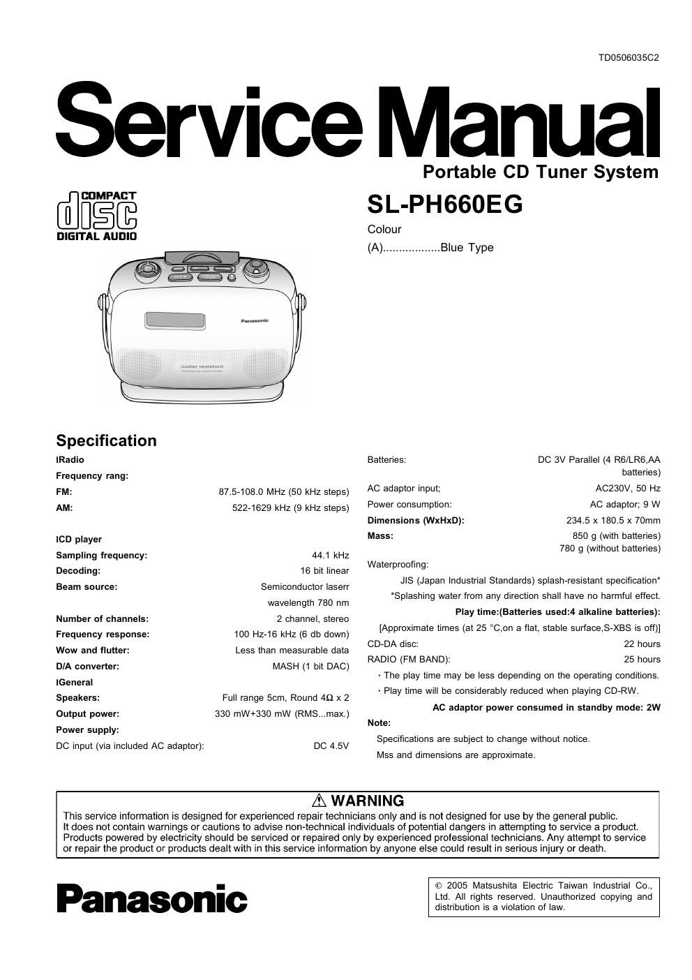
panasonic sl ph 660 eg service manual

Extracted text from panasonic sl ph 660 eg service manual (Ocr-read)


Page 1

TD050603502

Service Manual

@figé

DIGITAL AUDIO

Specification
Radio

Frequency rang:

FM:

AM:

lCD player
Sampling frequency:
Decoding:

Beam source:

Number of channels:
Frequency response:
Wow and flutter:

DIA converter:
lGeneral

Speakers:

Output power:
Power supply:

DC input (via included AC adaptor):

87.5-108.0 MHz (50 kHz steps)
522-1629 kHz (9 kHz steps)

44.1 kHz

16 bit linear

Semiconductor laserr
wavelength 780 nm

2 channel, stereo

100 Hz-16 kHz (6 db down)
Less than measurable data
MASH (1 bit DAC)

Full range 5cm, Round 49 x 2
330 mW+330 mW (RMS...max.)

DC 4.5V

Portable CD Tuner System
SL-PH660EG

Colour

(A)-

..Blue Type

Batteries: DC 3V Parallel (4 R6/LR6,AA
batteries)

ACZBOV, 50 Hz
AC adaptor; 9 W
Dimensions (WxHxD): 234.5 x 180.5 x 70mm

Mass: 850 g (with batteries)
780 9 (without batteries)

AC adaptor input;
Power consumption:

Waterproofing:
.118 (Japan Industrial Standards) splash-resistant specification
"Splashing water from any direction shall have no harmful effect.
Play time:(Batteries used:4 alkaline batteries):
[Approximate times (at 25 °C,on a flat, stable surface,S-XBS is off)]
CD-DA disc: 22 hours
RADIO (FM BAND): 25 hours
- The play time may be less depending on the operating conditions.
- Play time will be considerably reduced when playing CD-RW.
AC adaptor power consumed in standby mode: 2W
Note:
Specifications are subject to change without notice.
Mss and dimensions are approximate.

AWARNING

This service information is designed for experienced repair technicians only and is not designed for use by the general public.

It does not contain warnings or cautions to advise non-technical individuals of potential dangers in attempting to service a product.
Products powered by electricity should be serviced or repaired only by experienced professional technicians Any attempt to service
or repair the product or products dealt with in this service information by anyone else could result in serious injury or death

Panasonic

© 2005 Matsushita Electric Taiwan Industrial Co.,
Ltd. All rights reserved. Unauthorized copying and
distribution is a violation of law.

Page 2

SL-PHGGUEG

CONTENTS

1 Accessories ----------------------

2 Precaution of Laser Diode 2
3 Location of Controls --------- 4
4 Handling Precautions for Traverse Deck ................................ 5
4.1. Handling of traverse deck (optical pick-up) ...................... 5
4.2. CautiOn when replacing traverse deck ............................. 5
4.3. Grounding for electrostatic breakdown prevention ............ 5

5 Operation Checks and Component Replacement Procedures6
5.1. Remove of the CD Lid --------------------------------------------------- 6
5.2. Remove of the Lock Cover --------------------------------------------- 6

5.3. Removal of the Battery cover ------

5.4. Removal of the Rear cabinet ass D

5.5. Removal of the Operation chassis piece and Operation

P.C.B. ass [I ----------------------------------------------------------------- 7
5.6. Removal of the Operation P.C.B. (A) and Operation

P.C.B. (B) ---------------------------------------------------------------------- 7
5.7. Removal of the Speaker cups and Speakers ------------------- 7
5.8. Removal of the LCD P.C.B. -------------------------------------------- 8
5.9. Removal of the CAB gum ----------------------------------------------- 8

5.10. Removal of the LCD ass D --
5.11. Removal of the Main P.C.B

5.12. Removal of the Traverse Deck Unit

5.13. Replacement for the traverse motor -------------------------------- 9
5.14. Replacement for the optical pickup ------------------------------- 10
5.15. Removal of the Push knob ------------------------------------------- 10
5.16. Removal of the Jack P.C.B. and Piece (A) and Piece (8)
----------------------------------------------------------------------------------- 11
5.17. Removal of the Handle ------------------------------------------------- 11
5.18. Removal of the up Ornament ---------------------------------------- 11

1 Accessories

- AC adapter ............................................................... 1 pc.
(RFEA455E-S)

2 Precaution of Laser Diode

CAUTION:

5.19. Removal of the Volume knob ....................

5.20. Notice for assembling the volume knob link

5.21. Remove of the Operation button ...............
6 Troubleshooting guide ---------------------------------------------------------- 12
7 Checking the Operation Problems on the Traverse Deck
(Optical Pickup) ....................................................... 13
8 Automatic Adjustment Results Display Function (Self-check
Function) ------------------------------------------------------------------------------- 14
8.1. How to display automatic adjustment results ................. 14

8.2. Display of automatic adjustment results (self-check

function) .....................
9 Type Illustration of ICES, Transistors and Diodes

10 Schematic Diagram Notes ................................

11 Schematic Diagram --------------------------------------------------------------- 15
12 Printed Circuit Board and Wiring Connection Diagram -------- 24
13 Block Diagram ............................................................. 28
14 Wiring Connection Diagram .................................................. 32
15 Measurements and Adjustments .......................................... 33

15.1. Tuner Section -------------------------------------------------------------- 33

15.2. Alignment Points --

16 Terminal Function of ICs --
16.1. lC201(C2BBGF000772): System Control/LCD Drive

152- |C302(AN22003A-NF): Servo Amplifier -------------------------- 35
16.3. ICSO1(MN6627888D): Servo Processor, Digital Signal

Processor. Digital Filter & D/A Converter ....................... 35

17 Cabinet Parts Location ......................................................... 37

18 Traverse Parts Location ........................................................ 33

19 Packaging --------------------------------------------------------------------- 39

20 Replacement Parts List ......................................................... 40

L.-

This unit utilizes a class 1 laser. Invisible laser radiation is emitted from the pickup lens when the unit is turned on:

1. Do not look directly into the pickup lens.

2. Do not use optical instruments to look at the pickup lens.

3. Do not adjust the preset variable resistor on the optical pickup.

4. Do not disassemble the optical pickup unit.

5. If the optical pickup is replaced, use the manufactures specified replacement pickup only.

6. Use of control or adjustments or performance of procedures other than those specified herin may result in hazardous